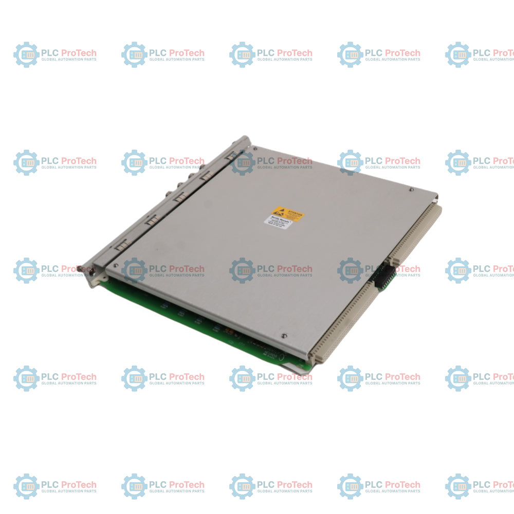
The Bently Nevada 3500/40M Proximitor Monitor is a four-channel module designed for continuous machinery protection and critical asset information monitoring. By accepting inputs from proximity transducers, the Bently Nevada 3500/40M conditions raw sensor signals to track essential dynamic parameters and compares them against user-programmable alarm setpoints. The primary engineering purpose of this unit is to drive automated machinery protection systems while delivering high-fidelity diagnostic data to operations and maintenance teams.
Key Features
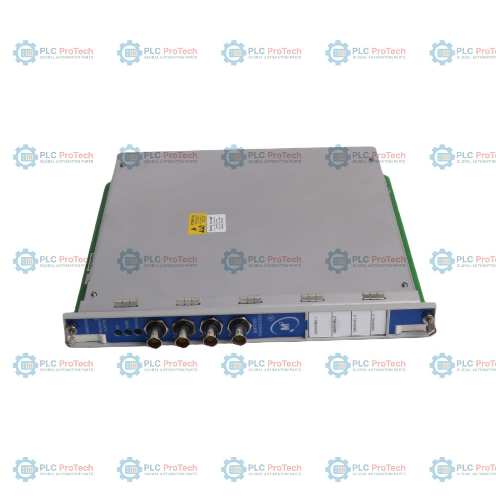
Four-Channel Design: Configurable in pairs, allowing dual-function allocation across channels 1 and 2, and channels 3 and 4.
Flexible Signal Conditioning: Supports diverse machine measurements via software configuration, including radial vibration, thrust position, eccentricity, differential expansion, and REBAM.
Advanced Setpoint Matrix: Allows Alert setpoints for all active static values and Danger setpoints for any two active static values per channel.
On-Board Status Tracking: Front panel LEDs indicate module health (OK), rack communication status (TX/RX), and active channel bypass conditions.
Short-Circuit Protection: Coaxial buffered transducer outputs on the front panel are fully protected against continuous wiring faults.
Industrial Applications
Steam and gas turbine shaft vibration and axial thrust monitoring.
Centrifugal and axial compressor protection systems.
Large industrial pump, fan, and electric motor diagnostics.
Rolling element bearing analysis using high-frequency REBAM configurations.
Ordering Information
| Option Code |
Description / Hardware Configuration |
| 3500/40M-A01-BXX |
Proximitor I/O Module with Internal Termination |
| 3500/40M-A02-BXX |
Proximitor I/O Module with External Terminations |
| 3500/40M-A03-BXX |
Proximitor I/O Module with Internal Barriers and Internal Terminations |
| Option B00 |
No Hazardous Area Approval |
| Option B01 |
CNRTLus Approval (Class I, Division 2) |
| Option B02 |
ATEX/IECEx/CSA Approval (Class I, Zone 2) - Only available with Option A03 |
Technical Specifications
| Parameter |
Engineering Specification |
| Signal Inputs |
Accepts 1 to 4 proximity transducer signals |
| Power Consumption |
7.7 Watts, typical |
| Input Impedance |
10 kOhm (Standard I/O Proximitor and acceleration inputs) |
| Buffered Output Impedance |
550 Ohm |
| Transducer Power Supply |
-24 Vdc |
| Radial / Thrust / Eccentricity Sensitivity |
3.94 mV/micrometer (100 mV/mil) or 7.87 mV/micrometer (200 mV/mil) |
| Differential Expansion Sensitivity |
0.394 mV/micrometer (10 mV/mil) or 0.787 mV/micrometer (20 mg/mil) |
| REBAM Sensitivity |
40 mV/micrometer (1000 mV/mil) or 80 mV/micrometer (2000 mV/mil) |
| Direct/Gap Filter Accuracy |
Within +/-0.33 percent of full-scale typical, +/-1 percent maximum |
| Phase Accuracy |
3 degrees error, maximum |
| Alarm Setpoint Accuracy |
Within 0.13 percent of the desired value |
| Operating Temperature (Standard I/O) |
-30 degC to +65 degC (-22 degF to +150 degF) |
| Operating Temperature (Barrier I/O) |
0 degC to +65 degC (32 degF to +150 degF) |
| Storage Temperature |
-40 degC to +85 degC (-40 degF to +185 degF) |
| Relative Humidity |
95 percent, non-condensing |
| Monitor Module Dimensions |
241.3 mm x 24.4 mm x 241.8 mm (9.50 in x 0.96 in x 9.52 in) |
| Rack Space Requirements |
1 full-height front slot (Monitor), 1 full-height rear slot (I/O Module) |
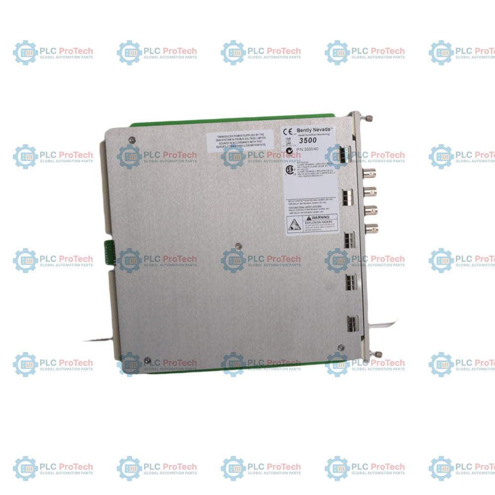
| Manufacturer |
Bently Nevada (Baker Hughes) |
| Country of Origin |
United States |
| Shipping Weight (Calculated) |
1.5 kg (Includes main module, rear I/O card, and protective packaging) |
| Package Dimensions (Calculated) |
300 mm x 280 mm x 65 mm |
Installation Guidelines
CRITICAL WARNING: Disconnect all power sources from the 3500 system rack before inserting or removing the monitor modules or rear I/O cards. High-voltage transients can destroy sensitive CMOS components. Ensure the field wiring is fully de-energized and appropriate lock-out/tag-out (LOTO) protocols are executed before disturbing terminal block connections.
1
Verify rack slot compatibility. The main 3500/40M monitor slide-in module must only be inserted into a full-height front slot, and its matching rear I/O module must align directly behind it in the corresponding full-height rear slot.
2
Seat the module firmly into the chassis guide rails. Gently push the front panel until the rear connectors hook securely into the backplane. Tighten the two integrated thumb screws on the front panel to ensure constant chassis grounding.
3
Wire the proximity transducer extensions to the rear I/O terminal strip or Euro-style connector header block. Avoid running low-voltage sensor lines parallel to high-current three-phase power cables to prevent electromagnetic noise injection.
4
Connect your engineering workstation to the rack via the 3500 Rack Configuration Software. Upload the baseline file, verify the specific transducer sensitivity settings (e.g., 200 mV/mil), and map the required channels to their respective protection relays.