Product Overview
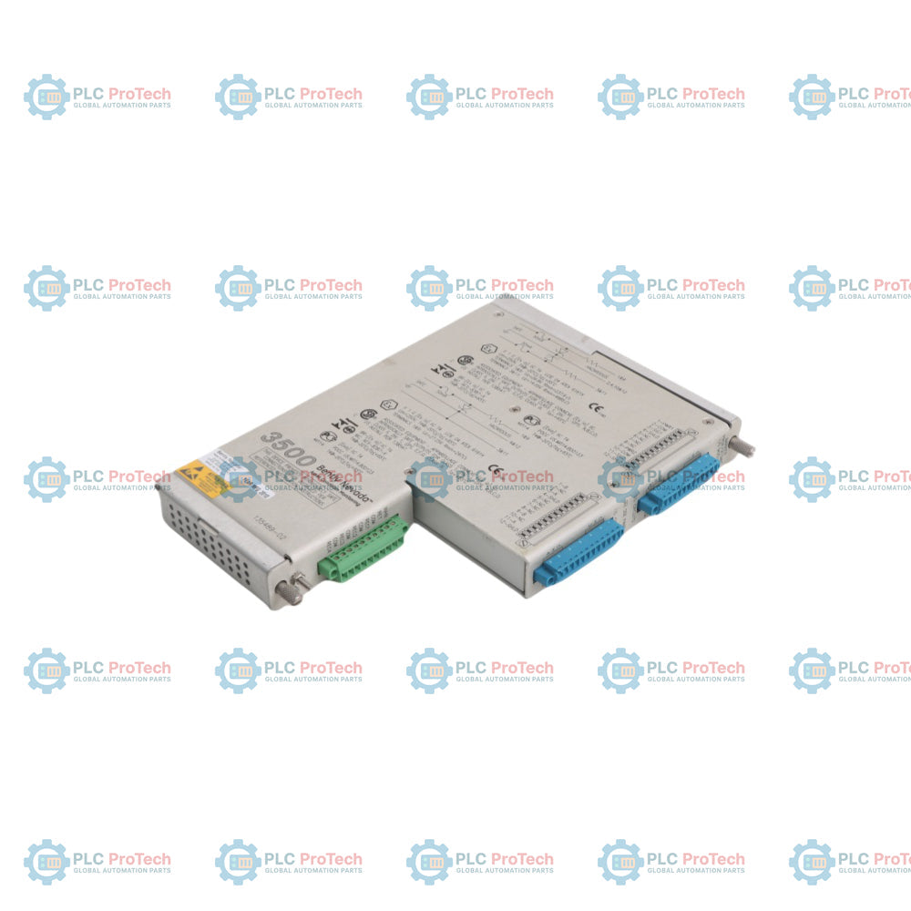
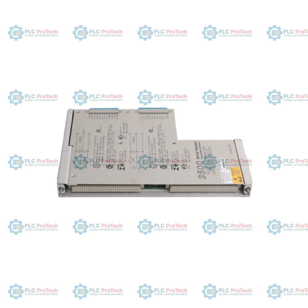
The Bently Nevada 135489-02 is a specialized 4-channel Proximitor Seismic I/O Module with Internal Intrinsic Safety Barriers and Internal Terminations designed for the 3500 Series Machinery Protection System. Seated in the rear slot of the 3500 instrumentation rack, this module serves as the direct hardware interface linking field-mounted sensors to the front-facing 3500/42M Proximitor Seismic Monitor module.
The hardware architecture provides two dedicated proximity/acceleration channels and two specialized Velomitor channels. Equipped with integrated Zener-type internal barriers, the 135489-02 restricts electrical fault energy traveling from the rack into the field, providing explosion-proof protection for transducers deployed in Class I, Division 1 or Zone 0 hazardous environments without the need for external galvanic isolation panels.
Technical Configuration
| Parameter |
Specification |
| Brand |
Bently Nevada |
| Model Number |
3500/42M (Rear Barrier Variant) |
| Part Number / ID |
135489-02 |
| Product Type |
Proximitor Seismic I/O Module with Internal Barriers |
| System Compatibility |
3500 Series Machinery Protection System |
| Channel Layout |
2 Proximity/Acceleration + 2 Velomitor channels |
| Safety Integration |
Built-in Intrinsic Safety Barriers (Internal Zener Barriers) |
| Termination |
Integrated Multi-position Screw Terminal Blocks |
| Supported Transducers |
3300 XL Proximity Probes, Accelerometers, Velomitors |
| Conditioned Values |
Radial Vibration, Thrust, Eccentricity, Velocity, Acceleration |
| Product Net Weight |
0.201 kg |
| Country of Origin |
United States (USA) |
Ordering Information
Machinery verification networks operating in hazardous processing environments require exact tracking of rear I/O card variation codes. Procure components matching the factory keys below.
-
Main System Core Monitor Type: 3500/42M
-
Factory Order Part Number: 135489-02
-
Associated Front Module Counterpart: 3500/42M Proximitor Seismic Processor Card
Engineering Notes & Field Wiring Guide
Hazardous Area Wiring and Barrier Safety
The 135489-02 card houses integrated explosion protection circuitry. Field wiring routing out from the module's terminal block must follow strict intrinsic safety segregation guidelines.
-
Clearance: Keep all intrinsically safe field transducer cables physically separated from non-intrinsically safe wires by a minimum clearance boundary of 50 mm (2.0 inches).
-
Dividers: Alternatively, install dedicated grounded metal dividers to avoid voltage arc induction.
Fixed Screw Terminal Allocation
Field cabling maps directly onto the built-in internal termination blocks. Use high-quality 3-wire twisted-shielded instrumentation cables (18 AWG to 22 AWG copper) to carry low-voltage displacement and acceleration paths.
-
Preparation: Strip individual conductor insulation jackets back exactly 7 mm.
-
Grounding: Connect outer grounding shields together and anchor them to the clean instrumentation earth rail at the structural cabinet bulkhead. Do not loop shield drain wires through the proximity signal common (COM) screws.
Configuration Handshake and Safety Restrictions
Because the 135489-02 limits terminal fault currents through precision internal barriers, plugging non-designated transducer loads into the channel pins can overload the internal Zener elements, destroying the protection loop. Prior to activating sensor excitation power, match the channel selection parameters (e.g., standard proximity probe versus Velomitor configuration) within the 3500 Rack Configuration Software to align with specific paired-channel hardware attributes.
Maintenance & Troubleshooting FAQ
Q: What is the primary difference between the 135489-02 and standard 3500/42M I/O modules?
A: The 135489-02 features built-in internal safety barriers. Standard I/O versions do not contain intrinsic insulation paths, requiring plants to source and mount independent, external barrier boards when routing sensor leads into classified hazardous plant fields.
Q: Why is the channel structure split into two distinct sensor pairs?
A: The hardware layout dictates specialized input electronics. Channels 1 and 2 are balanced to process voltage variables from high-frequency proximity probes or accelerometers, while Channels 3 and 4 feature targeted current loops designed specifically for active Velomitor-type velocity sensors.
Q: Can I hot-swap this rear I/O module while the 3500 rack is running?
A: While the front-facing 3500/42M card allows hot-swapping, extracting the rear 135489-02 while powered up breaks the physical sensor feedback loop and cuts excitation paths. This immediately triggers system interlocks and trips connected safety relays. Always change the rack security keyswitch to "PROGRAM" mode and establish channel bypass blocks before initiating hardware service.