Description
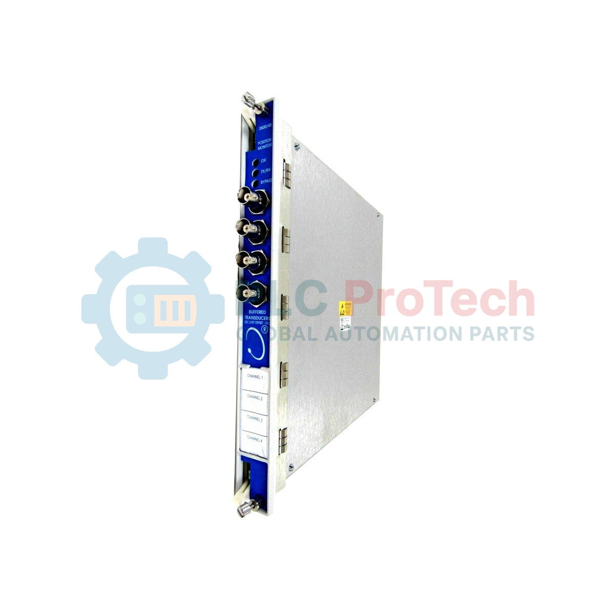
Providing continuous, high-accuracy machinery parameter tracking, the Bently Nevada 3500/45-01-CN functions as a core module within the 3500 Series Machinery Protection System. This 4-channel position monitor processes signals from various transducer types to measure thrust position, differential expansion, valve position, and case expansion. Configured with option 01, this unit features a Position I/O Module with Internal Terminations, designed for direct wiring of Proximitor sensors, Rotary Potentiometers (RPT), and DC Linear Variable Differential Transformers (DC LVDT) without requiring external terminal blocks. The CN suffix indicates specialized agency approvals, making this module fully compliant with country-specific industrial safety standards.
Features
- Four independent, fully programmable channels for versatile machinery position monitoring.
- Compatible with multiple input sensors, including proximity probes, rotary potentiometers, and DC LVDTs.
- Internal terminations design (Option 01) simplifies system architecture and minimizes cabinet space.
- Onboard alarms provide programmable alert and danger setpoints for real-time machinery protection.
- Continuous self-test utility continuously monitors sensor integrity and cabling faults.
Applications
- Steam and gas turbine control valve position tracking.
- Thrust bearing position monitoring on utility turbines and large compressors.
- Differential expansion tracking on high-temperature turbine casings.
- Structural and thermal growth measurement of critical process machinery.
Technical Specifications
| Parameter |
Specification Value |
| Manufacturer |
Bently Nevada |
| Model / SKU |
3500/45-01-CN |
| System Family |
3500 Series Machinery Protection System |
| Module Type |
Position Monitor |
| I/O Module Configuration |
Internal Terminations (Option 01) |
| Supported Sensors |
Proximitor, Rotary Potentiometer (RPT), DC LVDT |
| Number of Channels |
4 programmable channels |
| Agency Approvals |
CN (Country Specific Regulations) |
| Country of Origin |
U.S.A. |
| Shipping Weight (Calculated) |
1.15 kg (2.54 lbs) |
| Package Dimensions (Calculated) |
24.1 cm x 11.2 cm x 5.1 cm |
Empirical Engineering Insights
Alternative Models & Compatibility
This module with Internal Terminations (01) is not physically compatible with racks configured for External Termination blocks unless the corresponding rear I/O module is replaced. If converting from an older 3500/45 system with option 02 (External Terminations), ensure that the internal field wiring layouts are updated to match the direct terminal connections. Note that firmware version parity with your 3500 Rack Configuration Software is required; older configuration software versions may not support the CN-specific regional configuration parameters.
Application Pitfalls & Engineering Notes
When deploying DC LVDTs, ensure that the DC excitation voltage matches the transducer specification. Unstable DC power sources in adjacent cabinet spaces can inject electrical noise, leading to false position-trip alarms. For differential expansion setups, double-check configuration parameters: choosing the wrong sensor curve can lead to severe offset errors on steam turbine warm-up cycles.
Commissioning & Wiring Tips
Since the internal terminations option brings physical wiring directly to the rear of the rack, ensure proper cable strain relief is installed. Standard twisted, shielded pair cabling must be utilized for all position sensor runs. To prevent electrical ground loops that corrupt signal readings, ensure sensor shields are terminated strictly at the 3500 rack system ground, keeping the sensor-end shield completely insulated.
Installation Guidelines
CRITICAL WARNING
Disconnect all power sources supplying the 3500 rack before installing or removing the monitor module and its corresponding rear I/O card. Failure to de-energize can lead to electrostatic damage to internal components or trigger unintended protective trips on active control loops.
1
Ensure the selected slot at the rear of the rack matches the slot of the front monitor module. Install the rear I/O module first, securing the retaining screws.
2
Align the front monitor module with the card guides in the front slot. Slide the card in firmly until it seats in the backplane connector, and tighten the front panel screws.
3
Terminate the field wiring directly into the rear I/O screw terminals according to your project's specific wiring diagram, maintaining correct shield-to-ground isolation.
4
Power up the rack and use the 3500 Rack Configuration Software to configure channel types, alarm setpoints, and transducer scale factors.