The 990-05-50-02-01 provides continuous, proportional linear scaling of proximity probe signals into a simplified two-wire loop architecture. Engineered to serve industrial plant operators looking to streamline monitoring on high-speed assets, this compact component interfaces directly with standard machinery control infrastructure where basic alarm limits and process monitoring calculations are performed. By translating physical shaft movement into a standard analog format, it bridges the gap between field-level eddy current measurements and plant-wide control loops.
Constructed using a ruggedized, fully encapsulated potting compound, the unit functions safely when exposed to severe moisture, shifting temperatures, and airborne industrial contaminants. The system operates out of a single combined module housing, removing traditional multi-component panel steps and lowering the total hardware footings required inside remote field enclosures.
Features
Combined Signal Processing Housing: Houses the proximity measurement electronics and transmitter circuitry inside a unified enclosure to reduce total component counts.
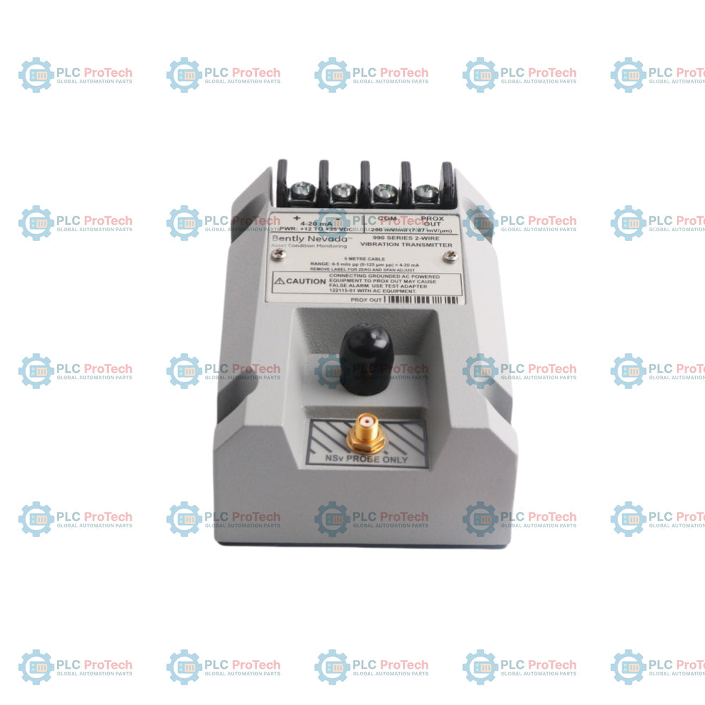
Raw Signal Accessibility: Provides unfiltered dynamic diagnostic measurements through a dedicated high-frequency coaxial port without altering the primary loop output.
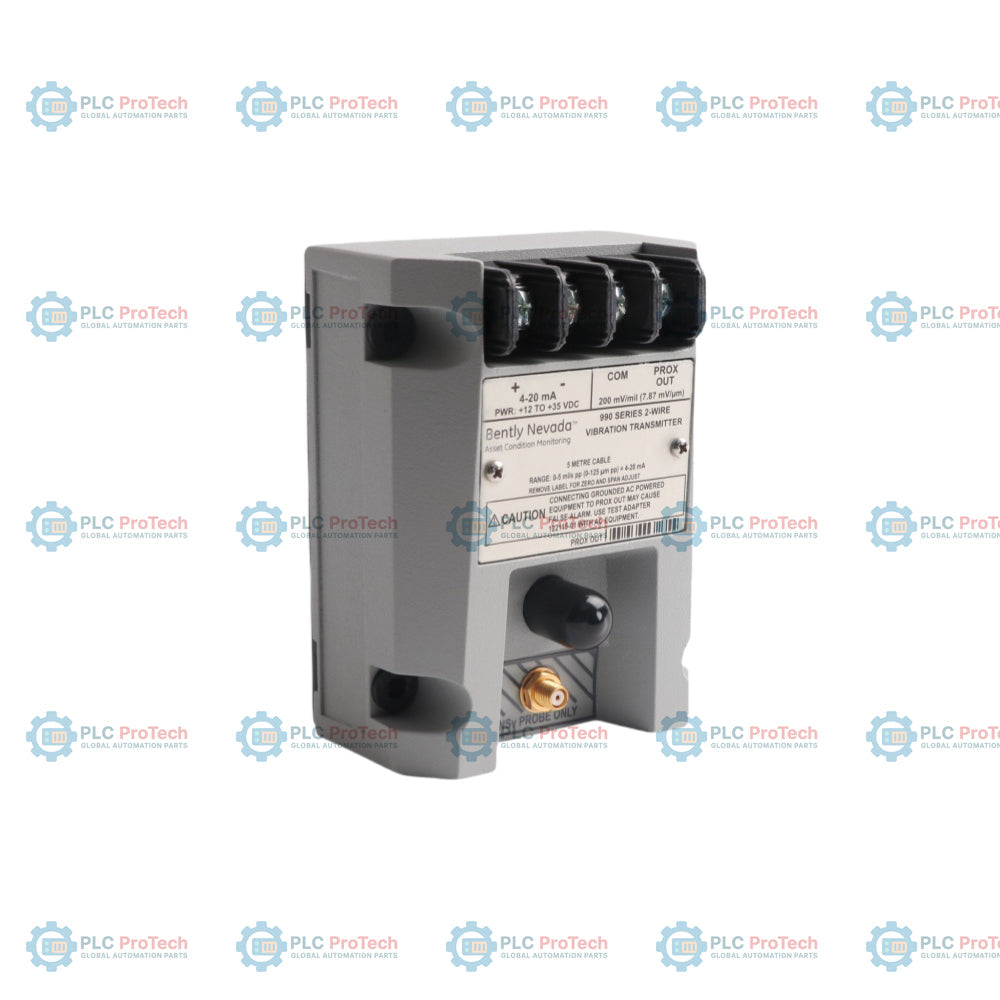
Front-Panel Leveling Potentiometers: Contains uncoupled, non-interacting zero and span trimpots situated safely beneath the environmental overlay label for straightforward device loop adjustments.
Loop Output Injection Test Pin: Includes an integrated verification path that allows external frequency signals to validate internal circuit operation and loop tracking.
Automatic Alarm Suppression Logic: Uses an intelligent Not OK fault verification system to swiftly drop loop current below 3.6 mA, ensuring field wiring degradation or probe breaks do not induce false trips.
High-Humidity Environmental Sealing: Features specialized internal potting that permits full 100% condensing humidity operation without degradation.
Integrated Bulkhead Hardware Integration: Comes factory-configured with rugged mounting bolts optimized for direct plate attachment.
Applications
High-speed centrifugal air compressors
Compact industrial process pumps
Medium and small electric induction motors
Industrial ventilation fans and exhaust blower systems
Accepts 1 single channel non-contacting 3300 NSv eddy current probe and matching cable
Supply Voltage Window
+12 Vdc to +35 Vdc input measured directly at the transmitter wire blocks
Current Loop Signal
2-wire configuration supplying 4 to 20 mAdc proportional to peak-to-peak displacement
Loop Error Allocation
Within ±1.5% of full-scale across a standard 250 ohm monitoring loop resistance
Target Proximity Gap
Mechanical installation gap between 0.5 and 1.75 mm (20 and 55 mils)
Impedance Constraints
1,000 ohms maximum loop resistance threshold at full 35 Vdc input power
Overcurrent Threshold
Limited internally to a maximum of 23 mA typical
Loop Fail-Safe Action
Output drops below 3.6 mA within 100 microseconds of a probe or connection fault
Fault Recovery Window
Restores normal analog tracking within 2 to 3 seconds after fault clearance
Power-On Stabilization
Drops output below 3.6 mA for 2 to 3 seconds during initial system power ramp-up
Dynamic Port Impedance
10 kohm calibrated source impedance configured specifically for a 10 Mohm testing load
Sensor Linear Field
1.4 mm (55 mils) total span beginning 0.25 mm (10 mils) away from target surface
Scale Factor Performance
7.87 mV/micrometer (200 mV/mil) ±6.5% typical based on an AISI 4140 steel target
Inherent Noise Floor
50 mV peak-to-peak typical noise level
Thermal Drift Deviation
Scale factor remains within ±10% of nominal from 0 degC to +70 degC (+32 degF to +158 degF)
Frequency Bandwidth
5 Hz to 6,000 Hz flat response with +0, -3 dB attenuation curves
Minimum Target Profiling
9.5 mm (0.375 in) minimum target surface diameter
Diagnostic Cable Limit
3 meters (10 feet) maximum physical cable distance for the coaxial BNC connection
Transmitter Ambient Limits
Operating: -35 degC to +85 degC; Storage: -52 degC to +100 degC
Transducer Temperature
Operating and Storage limits rated from -52 degC to +177 degC
Hardware Mass Metrics
Transmitter Unit: 0.43 kg (0.9 lbm); Total System: 0.82 kg (1.8 lbm) typical
Enclosure Composition
Sensor tip: Polyphenylene sulfide (PPS); Case body: AISI 303 or 304 Stainless Steel
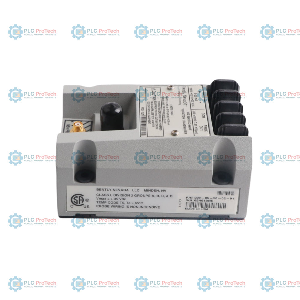
Product Manufacturer
Bently Nevada (A Baker Hughes Company)
Production Origin
United States of America
Connections/Interfaces
Wiring Pin Location
System Terminal Designation
Terminal E1
Loop Power Supply Positive Input (+) / 4 to 20 mA Connection
Terminal E2
Loop Power Supply Negative Input (-) / 4 to 20 mA Connection
Terminal E3
Non-Isolated Proximitor Dynamic Output (PROX OUT)
Terminal E4
Non-Isolated Proximitor Dynamic Common Reference (COM)
Coaxial J2 Plug
Front-Facing BNC Dynamic Signal Connection
Coaxial J3 Plug
Heavy Duty Integrated Proximity Probe Input Terminal
Installation Guidelines
Cable Selection Requirements: Run twisted-pair, shielded 1.0 mm2 (18 AWG) conductors for the primary 4 to 20 mA loop runs. The total length of this field loop wiring path can extend up to a maximum distance of 13 km (8 miles).
Loop Voltage Calculations: Verify field loop resistances do not violate the linear operational boundary formula: RLOOP = 43.5 x (Vps - 12). If total resistance exceeds this computed maximum, the transmitter cannot reach full-scale 20 mA transmission.
Diagnostic Port Phase Orientation: Note that the dynamic voltage signal supplied at the PROX OUT coaxial port is 180 degrees inverted relative to standard Bently Nevada instrumentation systems.
Ground Loop Protection: Do not interface standard mains-powered or non-isolated AC diagnostic instruments directly to the raw PROX OUT ports. Use the 122115-01 Test Adapter to introduce necessary isolation and maintain plant safety integrity.
Thread Coupling Restrictions: Ensure mechanical probe casings do not cross the absolute thread engagement maximum profiles (12 mm for M8x1 and 15 mm for M10x1) to eliminate permanent thread binding risks.
Compliance and Certifications
FCC Rules Enforcement: Verified under Part 15 of standard FCC interference regulations
Industrial EMC Performance: Certified to EN 61000-6-2, EN 61000-6-4, and the general EMC Directive 2014/30/EU
Explosive Atmosphere Directives: Compliant with ATEX Directive 2014/34/EU and RoHS Directive 2011/65/EU
Environmental Lifecycle Compliance: China RoHS 15-Year Environment Friendly Use Period (EFUP) specification under SJ/T 11364-2024
Marine Type Approvals: Certified under ABS 2009 Steel Vessels Rules criteria
North American Safety Marking: cNRTLus certified for Class I, Division 2, Groups A, B, C, and D hazardous fields (T5 @ Ta = +85 degC, Type 4 rating)
International ATEX/IECEx Classification:
II 1 G Ex ia IIC T4 Ga (T4 rating with Ta operational window of -30 degC to +85 degC)
II 3 G Ex ec IIC T4 Gc (T4 rating with Ta operational window of -30 degC to +85 degC)
FAQ
What is the practical consequence of exceeding the maximum calculated loop resistance?
When the circuit resistance exceeds the limit defined by the supply voltage formula, the system runs out of electrical headroom. As a result, the loop current becomes clamped and fails to reach the 20 mA full-scale limit during high vibration events.
Why does the analog loop current read under 3.6 mA immediately after applying power?
This is an automated power-up inhibit cycle that runs for 2 to 3 seconds. It holds the transmitter in a Not OK state to let internal circuits stabilize, preventing initial electrical switch-on spikes from being misread as vibration trips.
How does the integrated signal defeat logic handle a broken extension cable?
The transmitter recognizes the open circuit as a Not OK condition and immediately drops the analog loop current below 3.6 mA within 100 microseconds. This rapid drop alerts the attached PLC or DCS that the measurement channel has failed rather than reporting an actual machine over-vibration event.
Can standard diagnostic instruments be hooked directly up to the BNC terminal?
Only battery-powered or fully floating diagnostic instruments should be attached to the non-isolated PROX OUT port. Grounded, AC-powered instruments require the 122115-01 signal isolation adapter to prevent ground loops that could trigger false alarms on the loop network.
Maintenance data connects work orders, sensor signals, asset history, costs, and technician knowledge. Used well, it improves planning, reliability, predictive maintenance, spare-parts control, and...
This article explains how integrated electric actuators, such as SMC’s e-Actuator series, are transforming industrial motion control by replacing traditional pneumatic and hydraulic systems. It...
This article explains how PLC systems perform core mathematical operations such as addition, subtraction, multiplication, division, modulo, and exponentiation within industrial automation. It shows...
The article explains several advanced Boolean logic functions used in PLC programming beyond basic AND, OR, and NOT operations. It covers how tools like truth tables, multiplexers, pulse generators,...
Boolean logic is the foundation of every PLC program. From simple machine controls to complex industrial automation systems, logic gates determine how controllers respond to changing inputs and...
Industrial firewalls play a critical role in OT cybersecurity, protecting PLC, DCS, and SCADA networks through segmentation, ingress/egress control, and IDS/IPS integration aligned with IEC 62443...
Choosing a selection results in a full page refresh.