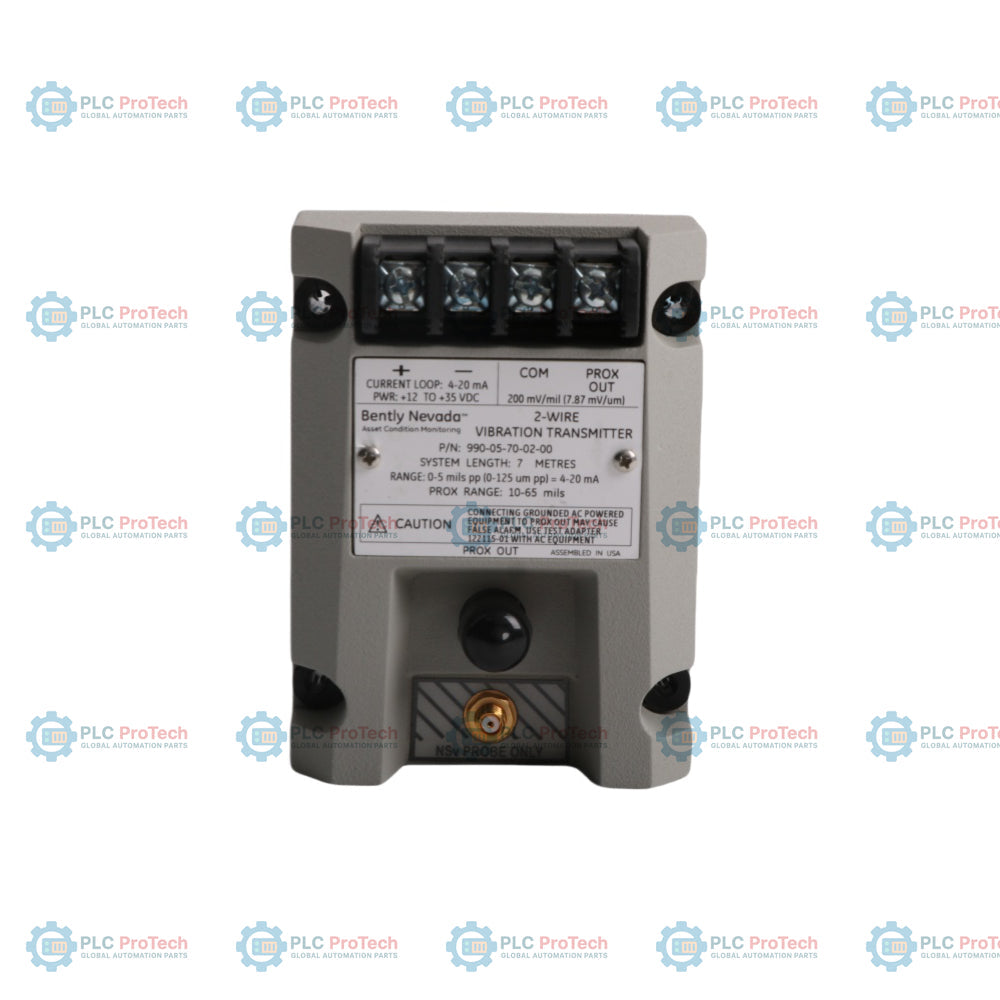
The Bently Nevada 990-05-70-02-00 is a two-wire, loop-powered 990 Vibration Transmitter designed to process signals from proximity probes into a proportional 4 to 20 mA industry-standard current loop. The device directly interfaces with a 3300 NSv proximity probe and its matching extension cable to monitor peak-to-peak vibration amplitude. This transmitter provides an engineered solution for machinery control systems where local control-level protection alarming and logic are required. It operates as an integrated Proximitor Sensor unit, optimizing signal processing for compact industrial equipment.
Features
Integrated Proximitor Sensor requires no external driver unit.
Non-isolated PROX OUT and COM terminals plus a coaxial connector deliver dynamic vibration and gap voltage signals.
Non-interacting zero and span potentiometers enable straightforward calibration and loop adjustment.
Test Input pin permits direct verification of the loop output using an external function generator.
Not OK/Signal Defeat circuit quickly drops output below 3.6 mA to suppress false alarms during probe faults.
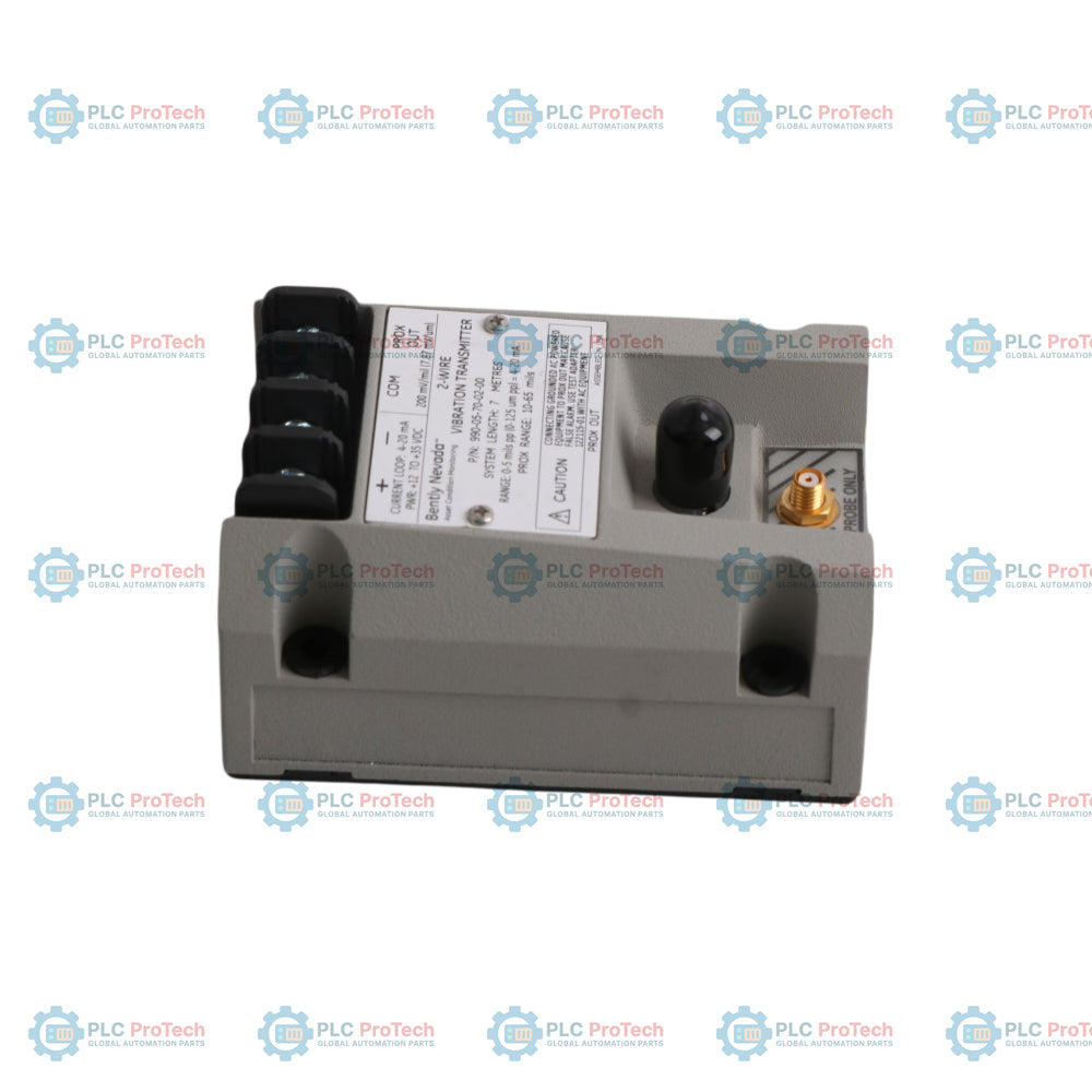
Potted construction provides robust environmental protection for high-humidity installations.
Compact design supports installation in confined spaces with minimal clearance.
Applications
Centrifugal air compressors
Small pumps and fluid machinery
Industrial electric motors
Cooling and ventilation fans
OEM machinery control system integration
Ordering Information
Suffix Code
Option Type
Field Description
990
Base Model
990 Vibration Transmitter
-05
A: Full-scale Option
0-5 mils pp (0-125 um pp)
-70
B: System Length Option
7.0 meters (23.0 feet)
-02
C: Mounting Option
Bulkhead screws
-00
D: Agency Approval Option
Not required
Technical Specifications
Category
Parameter
Specification
Identity
Manufacturer
Bently Nevada
Model
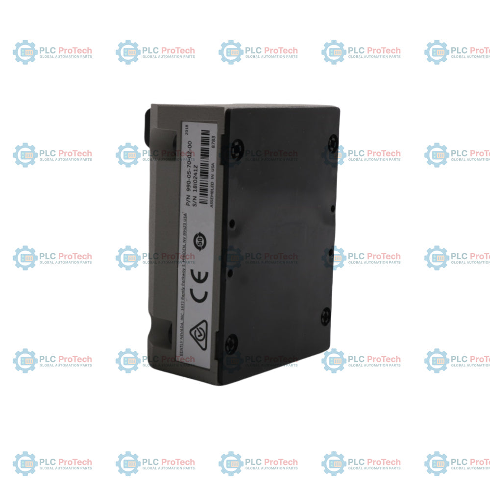
990-05-70-02-00
Electrical
Input
1 non-contacting 3300 NSv Proximity Probe and extension cable
Power Requirements
+12 to +35 Vdc input at the transmitter terminal
Signal Output
4 to 20 mAdc over specified full-scale range (2-wire configuration)
4 to 20 mA Loop Accuracy
Within +/-1.5% over specified full-scale range across 250 Ohm resistance
Maximum Loop Resistance
1,000 Ohm including cable at 35 Vdc
Current Limiting
23 mA typical
Zero and Span
Non-interacting external adjustments
NOT OK/Signal Defeat
Signal output < 3.6 mA within 100 us of fault; restores in 2-3 seconds
Power-up Inhibit
Signal output < 3.6 mA for 2 to 3 seconds after power application
Dynamic Performance
Prox Out Linear Range
1.4 mm (55 mils), begins approx. 0.25 mm (10 mils) from target
Prox Out Scale Factor
7.87 mV/um (200 mV/mil) +/-6.5% typical
Temperature Stability
Scale factor remains within +/-10% of 7.87 mV/um from 0 Celsius to +70 Celsius
Frequency Response
5 Hz to 6,000 Hz +0, -3 dB
Minimum Target Size
9.5 mm (0.375 in) diameter
Environmental
Transmitter Operating Temp
-35 Celsius to +85 Celsius (-31 Fahrenheit to +185 Fahrenheit)
Transmitter Storage Temp
-52 Celsius to +100 Celsius (-62 Fahrenheit to +212 Fahrenheit)
Probe Operating/Storage Temp
-52 Celsius to +177 Celsius (-62 Fahrenheit to +351 Fahrenheit)
+12 to +35 Vdc Loop Power Input and 4-20 mA Signal Output
PROX OUT Terminal
Non-isolated dynamic transducer signal for local diagnostic connections
COM Terminal
Common reference point for signal verification
Coaxial Connector
BNC connection for dynamic vibration and gap voltage monitoring (Max 3m distance)
Test Input Pin
Signal injection point for verifying loop response via a function generator
Installation Guidelines
Probe Gap Adjustment
The proximity probe must be physically gapped between 0.5 and 1.75 mm (20 and 55 mils) from the target surface. This ensures the target remains inside the transmitter's linear measurement range during machine operation.
Thread Engagement Limits
Do not exceed the maximum thread engagement lengths during installation to avoid component binding. For 1/4-28 threads, the limit is 0.375 inches; for M8x1 threads, the limit is 12 mm. Bently Nevada does not cover warranty replacements for probes damaged by excessive thread engagement.
Moisture Protection
The unit utilizes potted construction suitable for up to 100% condensing humidity. To maintain loop integrity, all coaxial connectors must be protected against direct moisture ingress using appropriate sealing boots or enclosures.
Signal Isolation and Test Adapters
The PROX OUT coaxial connector is non-isolated from the 4 to 20 mA loop circuit. While compatible with ungrounded, portable test equipment, you must use a 122115-01 or 990/991 Test Adapter when connecting to grounded, ac-powered test equipment like oscilloscopes to isolate the loops and maintain safety integrity.
FAQ
What limitations do vibration transmitters have compared to standard machinery protection monitors?
Transmitters provide peak-to-peak trending data only and cannot capture dynamic waveforms during an alarm event. They do not support phase tracking, gap alarms, Timed OK channel defeat, Danger Bypass, or Trip Multiply, and they cannot interface with plant-wide diagnostic platforms like System 1.
How does the Not OK circuit manage loose sensor connections?
If a probe connection loosens or fails, the transmitter drops the loop output below 3.6 mA within 100 microseconds. Once the connection is secure, the transmitter waits 2 to 3 seconds before restoring the standard output signal.
What size target is required for the transmitter to meet its accuracy specification?
The target must have a minimum diameter of 9.5 mm (0.375 inches) and be composed of AISI 4140 steel to maintain the calibrated scale factor.
Maintenance data connects work orders, sensor signals, asset history, costs, and technician knowledge. Used well, it improves planning, reliability, predictive maintenance, spare-parts control, and...
This article explains how integrated electric actuators, such as SMC’s e-Actuator series, are transforming industrial motion control by replacing traditional pneumatic and hydraulic systems. It...
This article explains how PLC systems perform core mathematical operations such as addition, subtraction, multiplication, division, modulo, and exponentiation within industrial automation. It shows...
The article explains several advanced Boolean logic functions used in PLC programming beyond basic AND, OR, and NOT operations. It covers how tools like truth tables, multiplexers, pulse generators,...
Boolean logic is the foundation of every PLC program. From simple machine controls to complex industrial automation systems, logic gates determine how controllers respond to changing inputs and...
Industrial firewalls play a critical role in OT cybersecurity, protecting PLC, DCS, and SCADA networks through segmentation, ingress/egress control, and IDS/IPS integration aligned with IEC 62443...
Choosing a selection results in a full page refresh.