Description
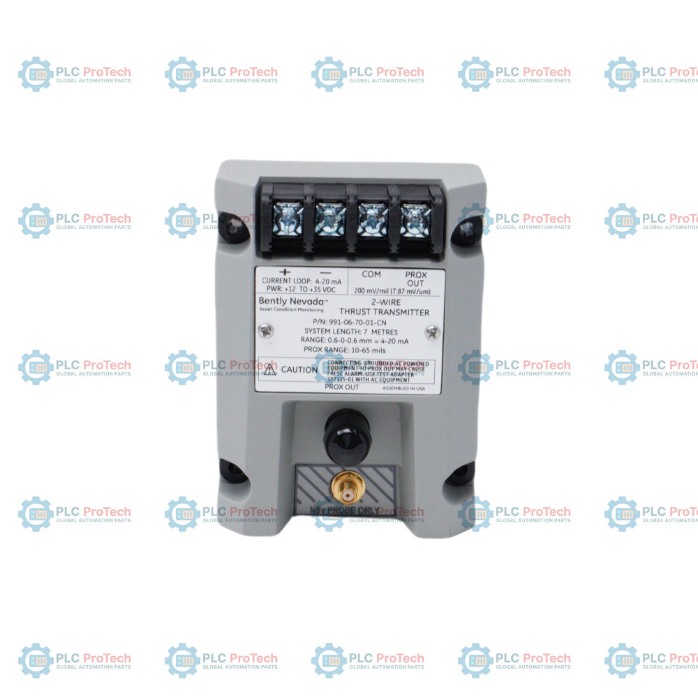
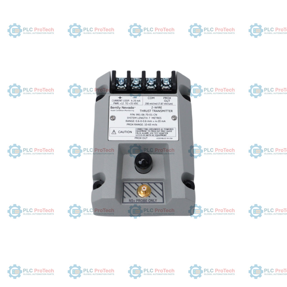
The Bently Nevada 991-06-70-02-01 is a 2-wire, loop-powered Thrust Transmitter designed to process signals from a proximity probe system to measure axial shaft position or thrust displacement on rotating machinery. This device conditions the raw signal into a standard 4 to 20 mA analog output proportional to the total target movement. It is engineered to interface directly with control systems like PLC or DCS architectures without requiring a separate monitor rack, providing a cost-effective setup for critical machinery protection. The unit is optimized for integration with compatible proximity transducers to ensure accurate, high-speed axial displacement monitoring in industrial environments.
Features
- Loop-powered 2-wire design simplifies field wiring and lowers installation costs.
- Direct 4 to 20 mA analog output interfaces seamlessly with PLCs and DCS systems.
- Non-contacting eddy current measurement principle provides long-term reliability.
- Dedicated BNC connector provides buffered raw voltage signal for diagnostics.
- Compact DIN rail mountable design saves control cabinet space.
Applications
- Axial thrust displacement monitoring on centrifugal compressors
- Steam and gas turbine rotor axial position tracking
- Boiler feed pump shaft monitoring
- Industrial gearbox thrust bearing wear evaluation
- High-speed fan and blower shaft positioning
Ordering Information
- 991: Thrust Transmitter
- 06: 3300 XL 8 mm proximity probe compatibility with 1.0 mm linear range
- 70: 7.0 metres system length option
- 02: 35 mm DIN rail mounting option
- 01: Multi-approval option (ATEX, IECEx, CSA)
Technical Specifications
| Parameter |
Specification |
| Manufacturer |
Bently Nevada |
| Country of Origin |
United States |
| Product Type |
Thrust Transmitter |
| Output Signal |
4 to 20 mA DC |
| Power Requirements |
17 to 30 VDC |
| Scale Factor |
4 mA/mm (or equivalent mil-based calibration) |
| Operating Temperature Range |
-35 to +85 Celsius |
| Storage Temperature Range |
-40 to +100 Celsius |
| Housing Material |
Zinc-plated steel or specialized polymer |
| Mounting Type |
35 mm DIN rail mount |
| Estimated Weight |
0.43 kg |
| Dimensions |
25.4 mm width x 112 mm height x 99 mm depth |
Connections / Interfaces
| Connector Pin |
Function |
| +4-20mA / +VTX |
Positive Power / Loop Current Input |
| -4-20mA / -VTX |
Negative Power / Loop Current Return |
| PROX |
Proximity Probe Signal Input Terminal |
| COM |
Common Reference Terminal |
| SHLD |
Shield / Earth Ground Terminal |
| BNC Jack |
Buffered Raw Voltage Output (10.2 mV/micrometer) |
Installation Guidelines
-
DIN Rail Mounting: Clip the transmitter securely onto a grounded 35 mm DIN rail inside an IP54 or better enclosure to protect against dust and water entry.
-
Shield Termination: Connect the transducer cable shields to the transmitter SHLD terminal, and ensure the control loop shield is grounded at the DCS/PLC side only.
-
Probe Gap Adjustment: Ensure the associated proximity probe is mechanically adjusted to its physical mid-range voltage before calibrating the 4 to 20 mA zero-point.
-
Cable Routing: Separate the input proximity probe cables and output current loop cables from high-voltage AC lines to prevent magnetic noise coupling.
-
Power Supply Polarity: Verify loop voltage polarity before energizing to prevent damage to the internal protection diodes.
Compliance and Certifications
FAQ
What is the primary function of this transmitter?
It converts raw proximity probe signals into a proportional 4 to 20 mA current loop for tracking shaft axial displacement.
Does this device require a separate rack-based monitoring system?
No, it is intended to send data directly to a PLC or DCS, eliminating the need for dedicated rack monitors.
How do engineers collect raw dynamic vibration data from this unit?
A front-panel BNC jack provides local access to the unconditioned dynamic signal using standard portable data collectors.
What loop voltage is required to power the unit properly?
The transmitter operates efficiently within a standard loop supply voltage window of 17 to 30 VDC.
Can this unit be mounted directly on the machine housing?
It should be installed in a protected field junction box or control enclosure to minimize high-temperature exposure and excessive vibration.
What happens if the loop polarity is accidently reversed during wiring?
Internal reverse-polarity protection prevents component damage, though the unit will not output a current signal until corrected.
Is calibration required during initial installation?
The hardware comes factory calibrated to specific system lengths and probe types, requiring only gap verification during installation.
Can a 5-metre probe system be connected to a 7.0-metre transmitter option?
No, mismatching the electrical system length options will cause significant linearity errors and corrupt the accuracy of the output.
What is the significance of the multi-approval suffix option?
It certifies the transmitter for installation in specific hazardous areas under ATEX, IECEx, and CSA guidelines when installed with barriers.
How should electrical noise from variable frequency drives be handled?
Ensure all shields are intact, properly isolated from the machine ground, and tied exclusively to the proper instrument common rail.