Description
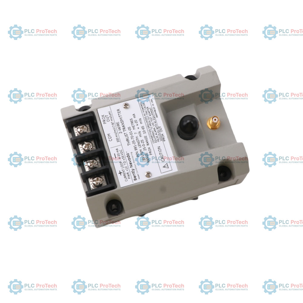
The Bently Nevada 991-25-70-03-05 991 Thrust Transmitter is a two-wire, loop-powered axial displacement transmitter designed primarily for Original Equipment Manufacturers (OEMs) of centrifugal air compressors, small pumps, motors, or fans. The device accepts a single input from a 3300 NSv proximity probe and its matching extension cable, conditioning the signal into an industry-standard 4 to 20 mA current loop output proportional to the shaft axial position (thrust) for direct integration into machinery control systems for protection and alarming.
The transmitter integrates the functionality of a Proximitor Sensor into a single unit, eliminating the need for an external independent sensor. Non-isolated PROX OUT and COM terminals, along with a coaxial BNC connector, provide a dynamic vibration and gap voltage signal for machinery diagnostics. The transmitter features a fully potted construction, allowing stable operation in high-humidity environments up to 100 percent condensing.
Features
- Integrated design combines the transmitter and Proximitor Sensor into a single unit.
- Standard 2-wire, loop-powered configuration provides a 4 to 20 mAdc signal proportional to full-scale axial displacement.
- Non-isolated PROX OUT, COM terminals, and BNC connector provide dynamic vibration and gap voltage outputs for field diagnostics.
- External, non-interacting zero and span potentiometers beneath the label facilitate easy loop adjustment.
- Test Input pin enables quick verification of the loop signal output using a variable DC voltage source.
- Power-up Inhibit circuit eliminates signal errors caused by line voltage transients during startup.
- Not OK / Signal Defeat circuit clamps output below 3.6 mA to prevent high outputs or false alarms caused by probe or cable faults.
- Fully potted housing accommodates high humidity and 100 percent condensing environments.
- Standard configuration includes 35 mm DIN rail clips and bulkhead mounting hardware.
Applications
- Centrifugal air compressors
- Small industrial pumps
- Industrial electric motors
- Industrial ventilation fans
- Rotor axial position (thrust) trend monitoring and machinery protection
Technical Specifications
Model Configuration (991-25-70-03-05)
Based on the Bently Nevada 991 series naming nomenclature, the specific model configuration parameters are decoded as follows:
| Option Position |
Configuration Item |
Technical Specification |
| AA |
Full-scale Option |
25-0-25 mils |
| BB |
System Length Option |
7.0 meters (23.0 feet) |
| CC |
Mounting Option |
DIN clips and screws |
| DD |
Agency Approval Option |
CSA Division 2, ATEX Zone 0, ATEX Zone 2, including ABS maritime approval |
Electrical
| Parameter |
Specification |
| Input Power |
Requires +12 to +35 Vdc at the transmitter terminals |
| Signal Output |
4 to 20 mAdc, 2-wire configuration |
| Loop Accuracy |
Typical ±1.5 percent over specified full-scale range (measured from TEST input to 250 ohm loop resistance) |
| Maximum Loop Resistance |
1,000 ohms maximum at 35 Vdc (including cable resistance). Formula: R_LOOP = 43.5 x (V_PS - 12) ohms |
| Current Limiting |
23 mA typical |
| Dynamic Output Impedance |
PROX OUT has a 10 kohm output impedance, calibrated for a 10 Mohm load |
| Linear Range |
0.25 to 1.65 mm (10 to 65 mils) at the PROX OUT interface |
| Incremental Scale Factor |
7.87 mV/micrometer (200 mV/mil) typical, ±6.5 percent including interchangeability error when measured against a flat AISI 4140 steel target |
| Temperature Stability |
Incremental Scale Factor remains within ±10 percent of 7.87 mV/micrometer (200 mV/mil) from 0 deg C to +70 deg C |
| Minimum Target Size |
9.5 mm (0.375 in) diameter |
Dynamic and Timing
| Parameter |
Specification |
| Not OK Delay |
Signal output drops below 3.6 mA within 100 microseconds after a Not OK condition occurs |
| OK Recovery Time |
Signal output returns to normal within 0.1 seconds after the Not OK condition is removed |
Environmental Limits
| Parameter |
Specification |
| Transmitter Operating Temperature |
-35 deg C to +85 deg C |
| Transmitter Storage Temperature |
-51 deg C to +100 deg C |
| Probe Operating Temperature |
-52 deg C to +177 deg C |
| Probe Storage Temperature |
-52 deg C to +177 deg C |
| Relative Humidity |
100 percent condensing, non-submerged operation (coaxial connectors must be protected) |
Mechanical
| Parameter |
Specification |
| Transmitter Weight |
0.43 kg (0.9 lbm) |
| Total System Weight |
0.82 kg (1.8 lbm) typical |
| Transmitter Case Material |
AISI 303 or 304 Stainless Steel (SST) |
| Probe Tip Material |
Polyphenylene Sulfide (PPS) |
| Probe Cable |
75 ohm coaxial cable, Fluorinated Ethylene Propylene (FEP) insulation |
| Tensile Strength |
222 N (50 lbf) maximum between probe case and probe lead |
Connections / Interfaces
Transmitter Terminal Blocks and Connectors
| Terminal Block / Connector |
Terminal Name |
Function |
| E1 |
PWR (Power) |
4-20 mA loop positive supply input (+17 to +35 Vdc) |
| E2 |
COM (Common) |
4-20 mA loop negative / common return |
| E3 |
PROX OUT |
Non-isolated dynamic signal output (maximum 3 meters of twisted pair cable) |
| E4 |
COM |
Dynamic signal common reference |
| J2 |
PROX OUT (BNC) |
Non-isolated dynamic coaxial BNC output for portable diagnostic equipment |
| J3 |
Probe Connector |
ClickLoc coaxial socket for connecting the proximity probe extension cable |
Installation Guidelines
- Cable Selection: For the 4 to 20 mA current loop between the transmitter and the receiver (PLC/DCS), use a shielded, twisted-pair, 1.0 mm sq (18 AWG) cable (part number 02173006). The maximum allowable length is 13 km (8 miles).
- Grounding and Shielding: The cable shield must be terminated to a single-point ground at the receiver end. The shield at the transmitter end must be insulated and isolated from the transmitter housing and local ground to prevent ground loops.
- PROX OUT Interface Isolation: The PROX OUT coaxial connector and terminals are not isolated from the 4 to 20 mA loop. Connecting grounded, AC-powered test equipment (such as oscilloscopes or analyzers) directly to PROX OUT can short the loop or introduce ground currents, leading to false thrust alarms or trips. Use the 122115-01 test adapter for AC-powered equipment.
- Signal Phase Characteristics: The phase of the PROX OUT dynamic signal is inverted compared to standard Bently Nevada Proximitor sensors. The 122115-01 test adapter inverts the signal to restore standard polarity conventions for external diagnostic equipment.
- Thread Engagement Limits: Ensure proper thread engagement when mounting the probe (e.g., maximum 0.375 inch engagement for 1/4-28 threads, and maximum 0.563 inch for 3/8-24 threads). Exceeding 1.5 times the nominal thread diameter may cause internal binding and damage the casing.
- Moisture Protection: While the transmitter housing is rated for 100 percent condensing relative humidity, it must not be submerged. All external coaxial connectors must be sealed using ClickLoc connector protectors (such as fluorosilicone sleeves) to prevent moisture or oil ingress.
- Loop Resistance Restrictions: Verify that the total loop resistance, R_LOOP, does not exceed the maximum allowed by the power supply voltage. If the loop resistance is too high, the transmitter will be unable to drive the full 20 mA output under maximum displacement conditions.
Compliance and Certifications
- FCC: Complies with FCC Rules Part 15.
- ATEX: Complies with ATEX Directive 2014/34/EU.
- RoHS: Complies with RoHS Directive 2011/65/EU.
- China RoHS: Environmentally Friendly Use Period (EFUP) is rated for 15 years per SJ/T 11364-2014.
- Maritime: Approved under the ABS 2009 Steel Vessels Rules.
- Canada and US Safety Approvals (cNRTLus):
- Class I, Division 2, Groups A, B, C, D; T5 at Ta = +85 deg C, Type 4 (when installed per drawing 128838).
- Hazardous Area Certifications (ATEX/IECEx):
- II 1G Ex ia IIC T4 Ga, T4 at Ta = -30 deg C to +85 deg C.
- II 3G Ex ec IIC T4 Gc, T4 at Ta = -30 deg C to +85 deg C.
- Intrinsic Safety Entity Parameters (Zone 0/1):
- Terminals E1-E2 (Power/Loop): U_i = 28 V, I_i = 120 mA, P_i = 0.84 W, C_i = 20 nF, L_i = 10 microhenries.
- Terminals E3-E4 and J2 Connector (Prox Output): U_o = 28 V, I_o = 6 mA, P_o = 0.17 W, C_o = 80 nF, L_o = 1 H.
- J3 Interface (Probe Connection): U_o = 28 V, I_o = 100 mA, P_o = 0.8 W, C_o = 27.3 nF, L_o = 5.3 mH.
FAQ
Q1: What are the primary logical functional limitations of the 991 transmitter compared to standard monitoring systems like the 3500 series?
A1: The 991 transmitter does not include complex monitoring logic such as Timed OK channel defeat, Danger Bypass, or Trip Multiply. Its analog 4-20 mA current output also prevents direct software-level integration with plant asset management platforms like System 1 or Rule Paks.
Q2: What is the calibrated measurement range for configuration 991-25-70-03-05?
A2: The "25" range option signifies a full-scale linear measuring range of 25-0-25 mils of axial displacement mapped to the 4 to 20 mA current loop.
Q3: What total system length is required for this specific configuration?
A3: The "70" system length option dictates that the transmitter must be used exclusively with a combined 7.0 meter (23.0 feet) 3300 NSv proximity probe and extension cable system. Mixing 5.0 meter system components will degrade the calibration and linearity.
Q4: What happens if an AC-powered oscilloscope is connected directly to the PROX OUT BNC jack?
A4: Because the PROX OUT connector ground is shared with the 4-20 mA loop return (COM), connecting an AC-powered instrument with a common ground can create ground loops or cause a short circuit, resulting in false thrust alarms or machinery trips at the control system.
Q5: How can external AC-powered diagnostic instruments be safely connected?
A5: Use the Bently Nevada 122115-01 test adapter. This adapter provides isolation between the transmitter circuit and the test instrument to eliminate ground loops while also inverting the signal 180 degrees to match standard instrument polarity.
Q6: What is the dynamic response time of the 991 current loop during a sensor fault?
A6: If a probe or cable open/short circuit causes a Not OK state, the output current drops below 3.6 mA within 100 microseconds. Once the fault is resolved, the loop recovers to an OK status within 0.1 seconds.
Q7: How does the power supply voltage affect the loop resistance capability of the transmitter?
A7: The transmitter requires between +12 Vdc and +35 Vdc at its terminals. The maximum allowable loop resistance (including wiring and safety barriers) is determined by the formula: R_LOOP = 43.5 x (V_PS - 12) ohms. Insufficient voltage or high resistance will clamp the maximum current output below 20 mA.
Q8: What is the function of the Test Input pin on the transmitter?
A8: The Test Input pin allows technicians to apply an external variable DC voltage source to simulate probe gap changes. This permits loop and alarm verification in the control system without removing or adjusting the physical proximity probe.
Q9: Do the Zero and Span potentiometers affect each other during calibration?
A9: No, the transmitter utilizes non-interacting potentiometers. Adjusting the zero position does not alter the span slope, and adjusting the span does not shift the zero point, simplifying the calibration process.
Q10: What is the maximum permissible distance for the loop output cabling?
A10: When using the recommended 1.0 mm sq (18 AWG) shielded twisted-pair cable and a 35 Vdc power supply, the current loop signal can be transmitted up to a maximum distance of 13 km (8 miles).
Q11: Can this specific model be installed in hazardous industrial locations?
A11: Yes, the "05" agency approval option provides a multi-agency certification suite. The unit can be installed in Class I, Division 2 environments or used as an intrinsically safe device (Ex ia IIC T4 Ga) in Zone 0/1 locations when wired through an approved safety barrier.
Q12: Why must the 991 transmitter be paired with a 3300 NSv probe instead of a standard 8mm probe?
A12: The internal conditioning circuitry of the 991 transmitter is calibrated for the electrical and physical characteristics of the 3300 NSv probe, which is designed for tight clearances and small counterbores. Connecting an 8mm probe will cause severe scale factor errors.
Q13: What protection is required for the coaxial connections in wet environments?
A13: Although the transmitter body is fully potted against 100 percent condensing humidity, the coaxial ClickLoc connectors between the probe and extension cable can suffer from signal attenuation if exposed to moisture or oil. They must be protected with fluorosilicone connector protectors.