Product Overview
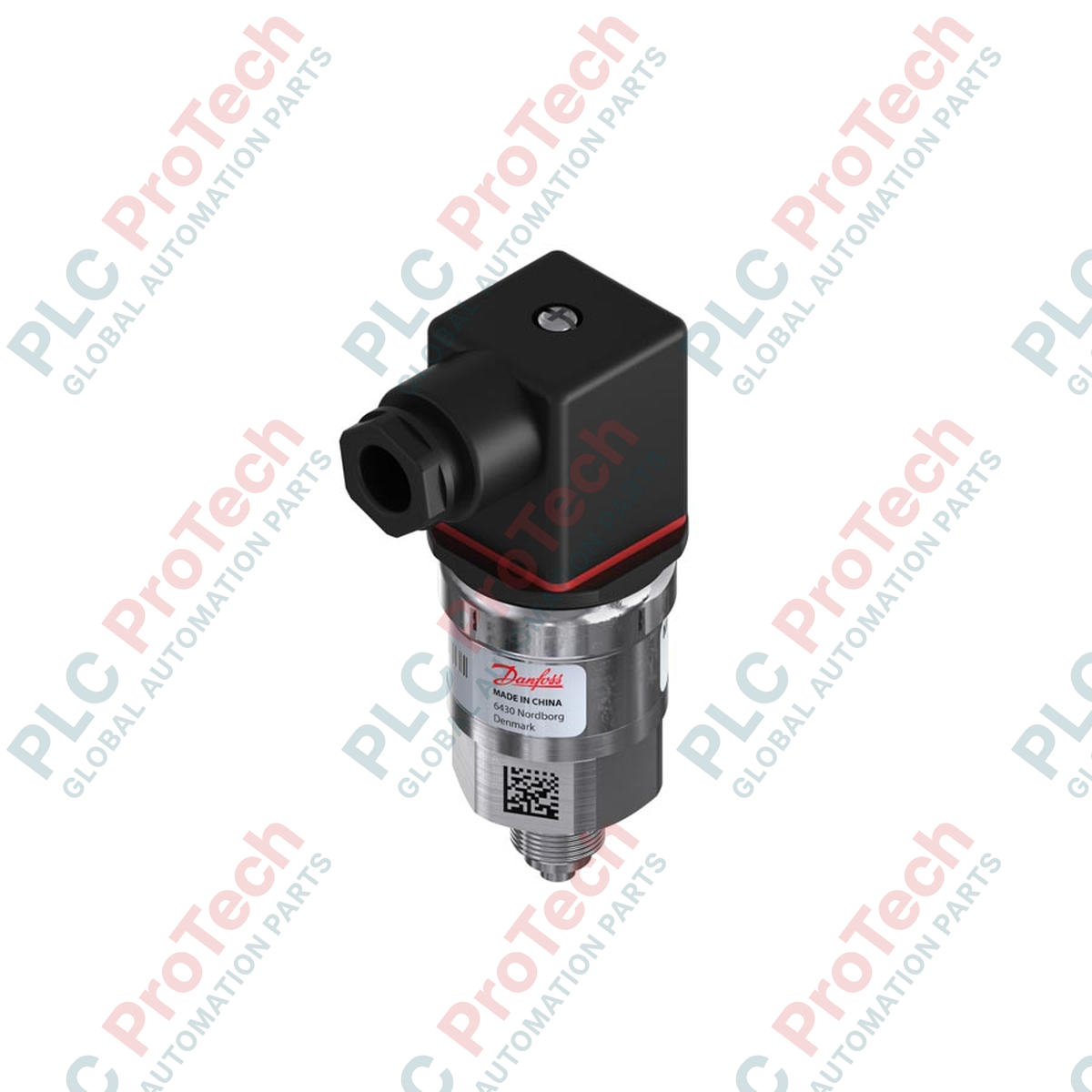
The 060G1372 (060G1372) is a robust pressure transmitter engineered for high-precision control in heavy industrial automation. Tailored for deployment in commercial boiler systems, cooling towers, hydraulic lines, and municipal water distribution networks, this field-tested instrument provides stable analog current feedback. By continuously monitoring pressure metrics and transmitting data to a central PLC or Distributed Control System (DCS), the sensor enables real-time optimization of pump speeds and valve positions. This precision tracking effectively minimizes fluid hammer risks, prevents cavitation anomalies, and helps avoid unpredicted plant shutdowns, ensuring maximum equipment efficiency.
Technical Configuration
The hardware features an acid-resistant stainless steel body containing a piezoresistive sensing element designed to resist mechanical shock and cyclic stress. To ensure long-term stability, the internal electronics utilize a fixed calibration framework that isolates the sensor from drift caused by ambient mechanical resonance. Integrated diagnostics enforce strict signal clipping thresholds between 3.6 mA and 22.4 mA, allowing automation controllers to instantly distinguish valid pressure fluctuations from wiring faults or signal shorts. The internal control board is further protected by an IP65-rated enclosure, shielding the circuitry from ambient humidity, splashing process water, and airborne particulates.
Technical Specifications
| Feature |
Specification |
| Model |
060G1372 |
| Brand |
Danfoss |
| Pressure Range |
0 to 40 bar |
| Output Loop |
4-20 mA |
| Precision |
+/- 0.5% (Typical) / +/- 1.0% (Max) |
| Overload Pressure |
100 bar |
| Process Thread |
G 1/4 Male (EN 837) |
| Operating Temp |
-40 to 100 deg C |
| Electrical Connector |
Pg 11 Angular |
| Ingress Protection |
IP65 |
| Weight |
Approx 1.5 kg |
FAQs
How do the integrated signal clipping parameters assist with diagnostics?
The sensor bounds its output; values shifting to 3.6 mA or 22.4 mA signify a fault. Because these values reside outside the standard 4-20 mA band, the supervising PLC can flag a field component defect without mistaking it for a legitimate process pressure change.
Does this gauge transmitter require atmospheric venting?
Yes. As a relative gauge transmitter, it references ambient atmospheric pressure. The reference channel is integrated into the connector structure, allowing the sensor to compensate for barometric fluctuations while maintaining an IP65 environmental seal.
Can the zero point be adjusted in the field?
No. This instrument utilizes a laser-welded, factory-sealed architecture with no mechanical trim potentiometers. This fixed design prevents calibration drift caused by continuous vibration and eliminates the risk of unauthorized field adjustments.
Mechanical Installation & Wiring Protocols
-
Process Port Mounting: Thread the G 1/4 male fitting into a port counter-bored to EN 837 specifications. Use a calibrated torque wrench on the 27 mm hex base to tighten the transmitter to 30-35 Nm. Do not rotate the upper cylindrical body by hand, as this risks breaking internal seal joints.
-
Terminal Interface: Terminate the positive power lead to Pin 1 and the negative return path to Pin 2 of the Pg 11 angular connector. Ensure the perimeter rubber seal is seated flush inside the connector cap before tightening the retaining screw to maintain the IP65 environmental seal.
-
Acoustic and Shock Mitigation: In systems with fast-cycling hydraulic loops or high-frequency piston pumps, install an upstream dampening orifice or siphon loop. While the sensor accommodates 100 bar surges, continuous exposure to cavitation peaks can degrade the structural integrity of the internal diaphragm.