Overview & Engineering Value
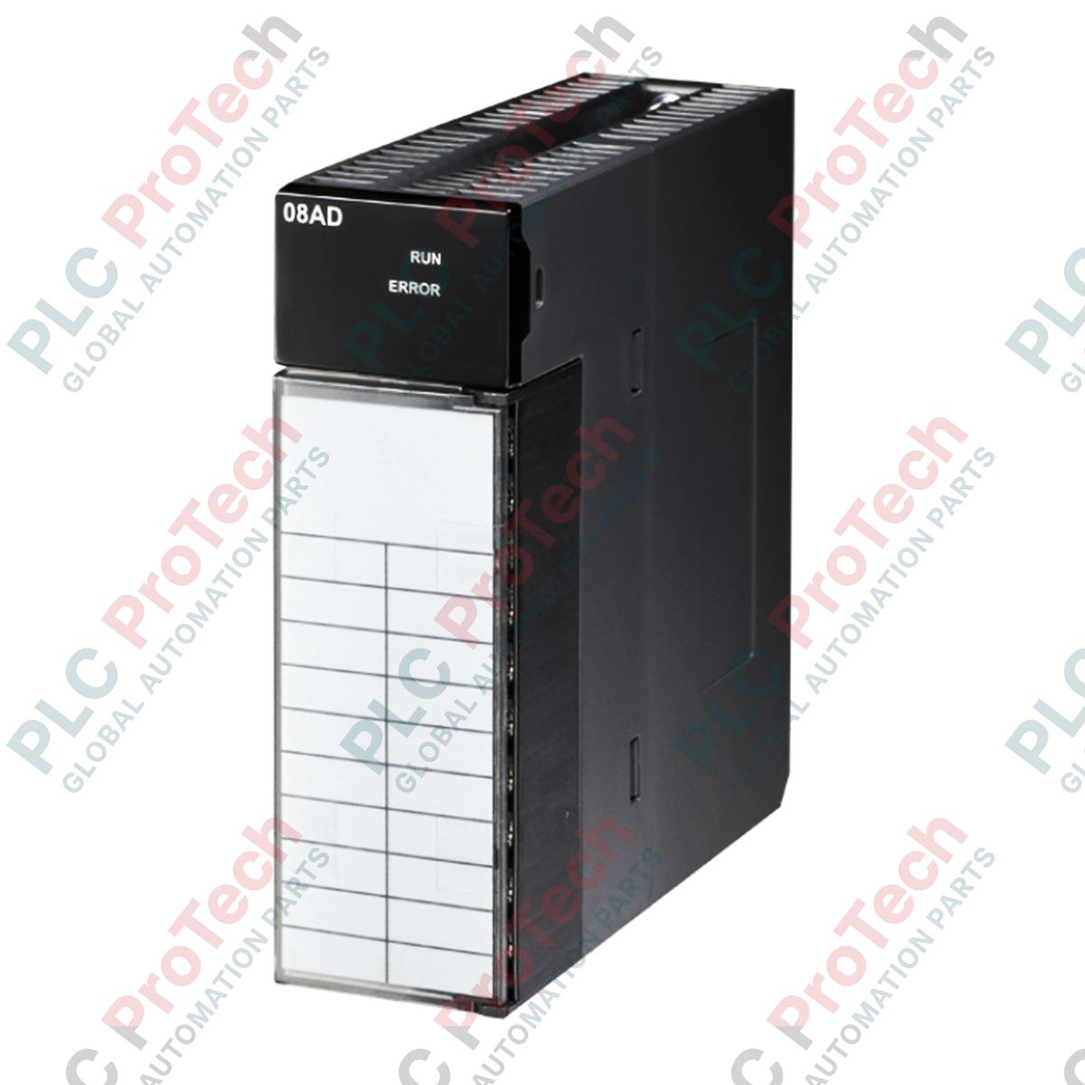
The AH08AD-5B (AH08AD5B) serves as a high-density analog input interface designed for the Delta AH500 series PLC platform. Built to handle demanding process control scenarios in industries such as wastewater treatment, petrochemical refining, and automated power distribution, this module guarantees precise data acquisition under harsh electrical conditions. By integrating eight high-resolution channels into a compact form factor, it minimizes cabinet space requirements while delivering exceptional noise immunity. The hot-swap functionality eliminates production line downtime during routine maintenance, allowing system integrators to replace modules without halting the central processing unit or interrupting critical sequential control operations.
System Configuration & Architectural Design
The hardware architecture of this module leverages an isolated signal design to decouple field-side loops from the sensitive internal logic circuits. This configuration effectively blocks ground loops and high-voltage transients common in industrial environments. Signal digitalization is managed via a high-performance 16-bit successive approximation register (SAR) analog-to-digital converter, providing fine-grained resolution for both voltage and current loops.
The embedded interrupt function allows the CPU to react instantaneously to critical process deviations, bypassing normal program scan times when a channel threshold is breached. Diagnostic capabilities are handled via integrated hardware registers that continuously monitor system health, wire disconnections, and out-of-range inputs, reporting real-time faults directly to the host controller via the backplane.
Hardware Specifications
| Parameter |
Specification Details |
| Model |
AH08AD-5B |
| Brand |
DELTA |
| Origin |
Taiwan |
| Number of Inputs |
8 channels |
| Signal Ranges (Voltage) |
0 to 1 V, 1 to 5 V, -5 to +5 V, 0 to 10 V, -10 to +10 V |
| Signal Ranges (Current) |
0 to 20 mA, 4 to 20 mA, -20 to +20 mA |
| Hardware Resolution |
16-bit |
| Conversion Speed |
150 microseconds / channel |
| Base Error (at 25 deg C) |
Voltage mode: +/-0.1%, Current mode: +/-0.1% |
| Base Error (Full Range) |
Voltage mode: +/-0.45%, Current mode: +/-0.2% |
| Linearity Error (at 25 deg C) |
Voltage mode: +/-0.07%, Current mode: +/-0.05% |
| Power Consumption |
1.9 W (Internal backplane power) |
| Isolation Method |
Optical isolation between digital and analog circuits |
| Terminal Connection |
JIS removable terminal block |
| Dimensions |
110 mm x 35 mm x 103 mm |
| Weight |
0.35 kg (Shipping Weight: 2.0 kg due to protective packaging) |
| Operating Temperature |
0 to 60 deg C |
Technical Queries & Troubleshooting
-
How does the module handle a combination of voltage and current inputs simultaneously?
The hardware supports mixed signal allocation across its 8 channels. Configuration is managed via the PLC programming software, where each channel can be independently mapped to match the field sensor's electrical output profile.
-
What actions should be taken if the module status LED indicates an error?
Check the internal diagnostic registers using the programming utility. A solid red error indicator typically points to an external power supply fault, an open circuit on a 4-20 mA current loop, or an input signal exceeding the maximum configured threshold.
-
Is the hot-swapping feature safe to use while the process is live?
Yes. The backplane interface is engineered with staged pin lengths to control inrush currents. The module can be removed or inserted while the rack is powered without risk of damaging the internal logic or disrupting neighboring I/O modules.
Field Commissioning & Safety Protocols
Shielding and Grounding Standards
To mitigate electromagnetic interference, all analog instrument cables must utilize twisted-pair conductors with an overall braided shield. Terminate the shield exclusively at the control cabinet ground bar using a low-impedance grounding clamp. Leaving the field-instrument end of the shield floating prevents the formation of ground loops that distort 16-bit signal conversion accuracy.
Terminal Block Torque and Wiring
When interfacing with the JIS removable terminal block, utilize insulated ferrule terminals to eliminate the risk of stray wire strands creating short circuits. Tighten all terminal screws to a maximum torque specification of 0.5 Nm. Avoid routing low-voltage analog signal lines within the same conduit or wire duct as high-voltage AC motor drive cables to prevent inductive noise coupling.
Thermal Management Guidelines
Maintain a minimum clearance of 50 mm above and below the module rack to ensure natural convective airflow. In enclosed control panels experiencing ambient temperatures near the upper limit of 60 deg C, forced ventilation or an active air conditioning system must be deployed to avoid thermal drifting of the internal analog references.