Industrial Application & Operational Value
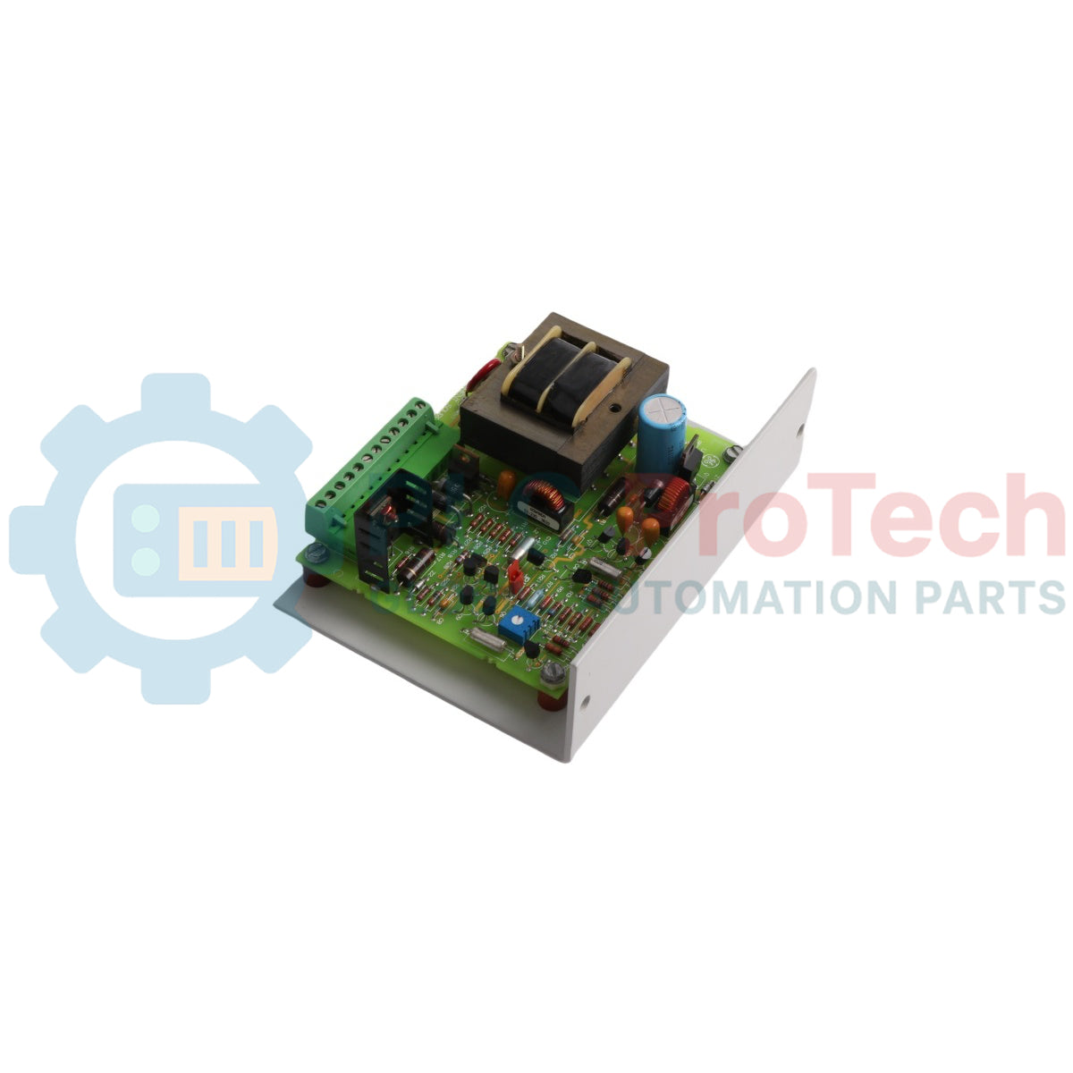
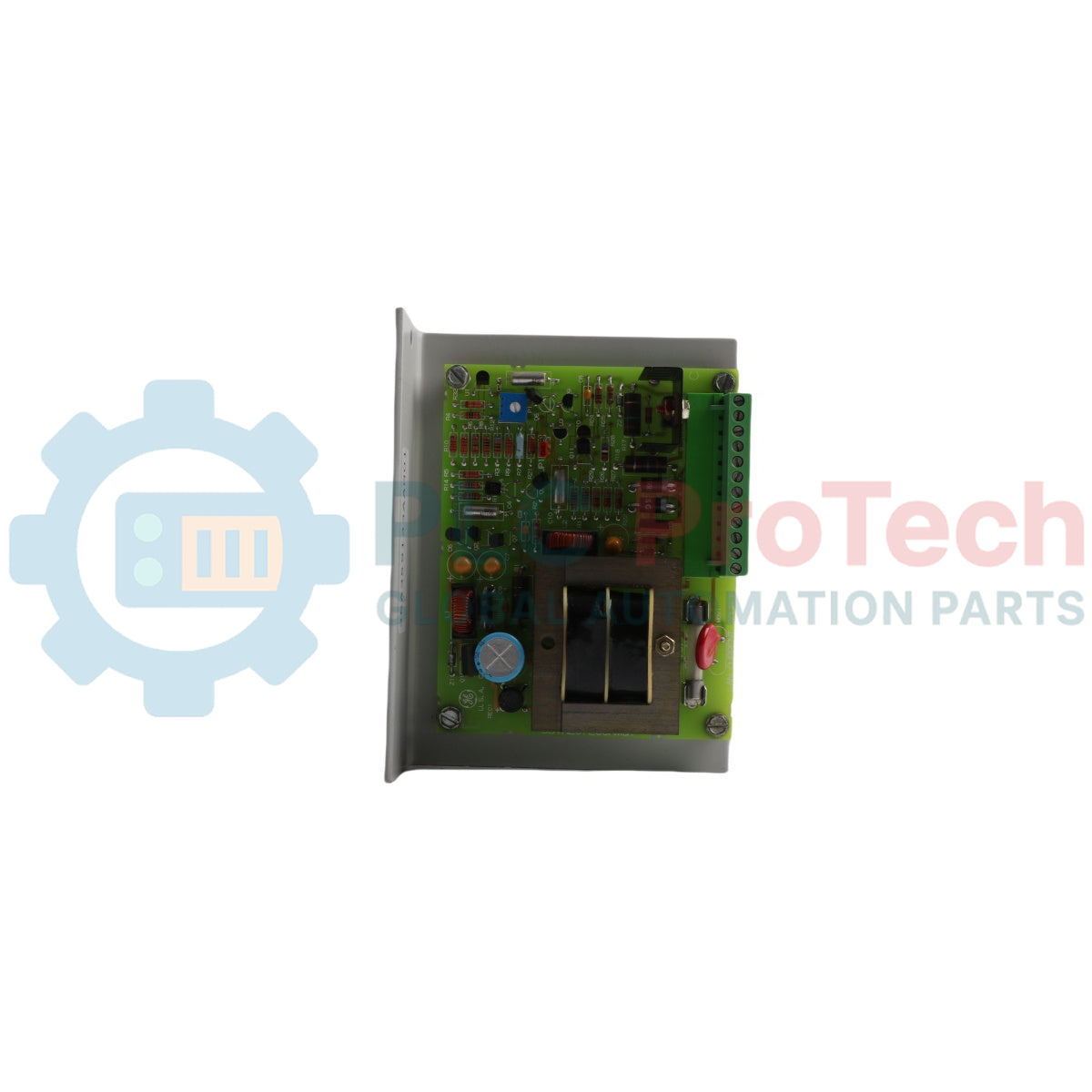
The 531X207LCSAMG1 (531X207LCSAMG1) is a ruggedized Local Area Network (LAN) Current Source Card engineered by General Electric for the legacy 531X drive conversion and exciter framework. Serving as a crucial power distribution node within complex drive cabinets, this circuit card assembly provides isolated, highly regulated power feeds directly to critical network communications boards. Heavy industries such as steel milling, power generation, and mining deployment centers rely on the 531X207LCSAMG1 (531X207LCSAMG1) to maintain uninterruptible data interfaces across critical control nodes. In multi-tier networking designs—such as dual-redundant iFIX architectures or dedicated SCADA failover setups handling real-time database synchronization—this card prevents network dropouts caused by localized power fluctuations. By securing reliable power to the communication plane, it safeguards real-time process monitoring, preserves system telemetry, and minimizes expensive, unplanned production stoppages.
Hardware Architecture & Topology Controls
The functional design of the 531X207LCSAMG1 power and communication interface card integrates onboard supply tailoring, signal routing, and fault mitigation structures.
-
Dual-Rail Voltage Delivery: Translates a fuse-protected 115 VAC line input into highly regulated 5 VDC and 15 VDC output tracks, perfectly matching the electrical requirements of the companion LAN board.
-
Manual Output Calibration: Features a multi-turn onboard potentiometer that enables precise electrical tuning of voltage levels, allowing field technicians to compensate for line impedance drops over extensive internal bus runs.
-
Configurable Selection Interface: Employs a rugged hardware jumper (designated as J1) that gives engineers explicit selection over the active power supply rails to accommodate specialized drive configurations.
-
Centralized Signal Terminations: Hosts a heavy-duty 12-point terminal board on its face that acts as the sole junction for all incoming primary power and outgoing communication control signals, simplifying troubleshooting.
Technical Metrics & Specifications
| Operational Parameter |
Engineering Specification |
| Model Identification |
531X207LCSAMG1 |
| Brand Manufacturer |
General Electric (GE Boards & Turbine Control) |
| Compatible Product Series |
531X Replacement Series (Drives & Exciters) |
| Module Classification |
Local Area Network Current Source Board |
| Primary Line Power Input |
115 VAC (Single Phase, Fuse Protected) |
| Regulated Secondary Outputs |
5 VDC and 15 VDC |
| Hardware Selection Links |
J1 Jumper Block for Output Configuration |
| Calibration Interface |
Onboard Voltage Adjust Potentiometer |
| Field Termination Node |
12-Point Fixed Screw Terminal Board |
| Built-in Overcurrent Shield |
Integrated Front-Facing Power Fuse |
| Surrounding Temperature Limits |
0 to 60 deg C |
| Physical Dimensions |
Standard GE 531X Rack-Mount Profile |
| Hardware Mass |
0.38 kg |
| Country of Origin |
United States |
Diagnostic Performance FAQs
How does the J1 hardware jumper alter the power distribution of the 531X207LCSAMG1?
The J1 jumper acts as the primary hardware selector between the 5 VDC and 15 VDC power rails supplied to the companion LAN communication board. Field personnel must position this jumper according to the system manual requirements of the specific drive or network transceiver module connected to the card.
What is the correct method for adjusting the voltage output if line drops occur inside the drive cabinet?
If multi-meter diagnostics at the 12-point terminal board show slight voltage drop-offs, technicians can turn the integrated multi-turn potentiometer on the card face. This potentiometer allows fine adjustments to the scaled DC outputs, aligning the supply voltages back to nominal 5 VDC or 15 VDC tolerances.
How does this card support SCADA database synchronization during network failures?
The card powers the underlying hardware that maintains redundant LAN paths (LAN 1 and LAN 2) for iFIX networking. By ensuring continuous power to the transceivers, it allows the system to instantly switch to secondary or tertiary communication paths if the primary SCADA server connection fails or drops offline, preserving database synchronization without dropping critical process data.
Field Engineering & Installation Protocol
-
Primary Power Isolation & Fuse Safeguards:
Turn off and lock out the primary 115 VAC power source before inserting, removing, or wiring the module. The incoming line power connects directly through the 12-point terminal block and represents a severe shock hazard. Always inspect the state of the integrated onboard fuse before commissioning the system; a blown fuse indicates an overcurrent draw or an internal component short circuit on the secondary DC rails.
-
Terminal Screw Torque and Wire Stripping:
Strip all field and power wires targeting the 12-point terminal board back by 8 mm to 10 mm. Ensure no loose copper strands protrude from the terminal mouth. Tighten the terminal screws to a maximum torque of 0.5 N-m (4.4 inch-lbs). Loose connections can cause localized heat buildup and electrical noise, which can interfere with nearby high-speed LAN data buses.
-
Potentiometer Calibration Rules:
Only use insulated, non-conductive adjustment screwdrivers when tuning the onboard calibration potentiometer while the board is powered. Using a standard metal tool risks accidental shorts against nearby live capacitor traces, which can ruin the voltage regulation sub-circuits and cause permanent damage to the connected LAN transceivers.