Technical Overview & Industrial Deployment
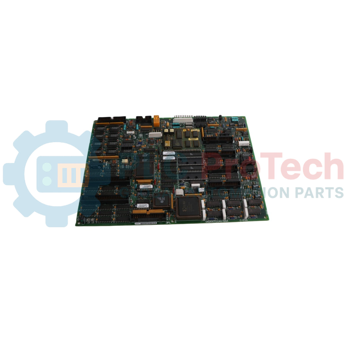
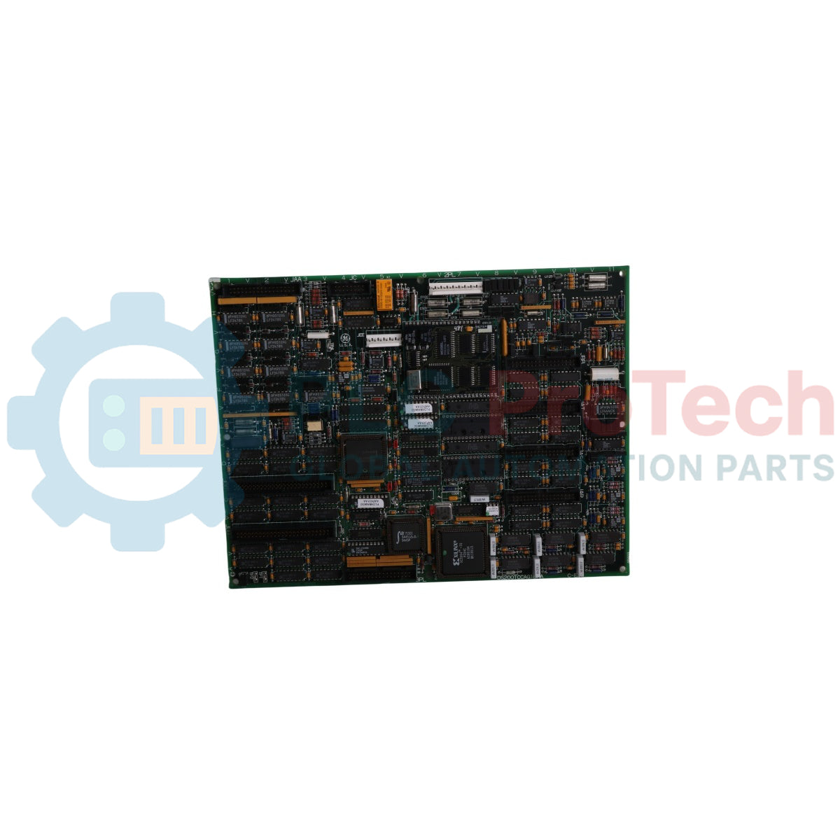
The DS200TCCAG1BAA (DS200TCCAG1BAA) is a core-level analog signal processing instrument developed by General Electric for the legacy Mark V Speedtronic gas and steam turbine control framework. Operating from the central R5 control core, this multi-layer interface board acts as the primary data aggregation node for high-precision telemetry, scaling and conditioning raw field inputs before transferring them to the system logic solvers. Power utilities, petrochemical refineries, and heavy mechanical drive plants deploy the DS200TCCAG1BAA (DS200TCCAG1BAA) to oversee delicate thermal profiles, multi-channel current loops, and rotational mechanical stability indicators. By unifying multi-source field signals into a single standardized bus structure, the board guarantees predictable governor behavior, shields heavy rotating turbines from sudden hunting or thermal fatigue, and minimizes unplanned operational downtime in heavy industrial setups.
Architectural Circuitry & Signal Mapping
The structural engineering of the DS200TCCAG1BAA board integrates discrete microprocessing logic with multi-functional acquisition sub-circuits.
-
Integrated Microcontroller Logic: Features an onboard Intel 80196 processor that executes independent signal conditioning algorithms, scaling raw field data locally using instructions saved within socketed, erasable Programmable Read-Only Memory (PROM) blocks.
-
Thermal Monitoring Infrastructure: Incorporates dedicated RTD excitation circuitry and cold-junction compensation calculations. It monitors RTD resistance shifts across the JCC and JDD connectors while translating thermocouple signals via the TBQA terminal board interface.
-
Dynamic Current Loop Management: Utilizes onboard burden resistors across the JBB connector path to drop incoming 4-20 mA transducer currents into readable voltage steps, while simultaneously sourcing regulated 4-20 mA current outputs through the JAA connector to drive remote instruments.
-
Turbine Shaft Telemetry: Hosts specialized shaft monitoring subsystems that continuously track electrical potential and current leakage across the turbine shaft, delivering vital insulation degradation telemetry to the central I/O engine through the 3PL bus.
Hardware Parameters & Operational Indexes
| System Parameter |
Factory Engineering Index |
| Model Designation |
DS200TCCAG1BAA (Parent Board: DS200TCCAG1) |
| Brand Identifier |
General Electric (GE Boards & Turbine Control) |
| Control System Series |
Speedtronic Mark V (TC2000 Subseries) |
| Functional Acronym |
TCCA Card |
| Core Mounting Location |
R5 Control Chassis Slot |
| Onboard Logic CPU |
16-Bit Intel 80196 Microprocessor |
| Firmware Storage Architecture |
Socketed, Removable PROM Modules |
| Primary Master Communication Link |
3PL Data Bus Connector (To STCA / I/O Engine) |
| Field Analog Input Sourcing |
4-20 mA Loops, Thermocouples, RTDs, Shaft Monitors |
| Physical Dimensions |
28.0 x 18.0 cm |
| Net Hardware Weight |
0.45 kg |
| Printed Circuit Protection |
Normal Industrial Grade Coating |
| Hardware Revision Hierarchy |
Functional Revisions B and A, Artwork Revision A |
| Operational Thermal Limits |
0 to 60 deg C |
| Logic Power Input Feed |
2PL Power Distribution Plug (Sourced via TCPS Board) |
| Country of Origin |
United States |
Technical Diagnostics FAQs
What are the primary functions of the onboard hardware jumpers J1, JP2, and JP3?
Jumper J1 controls the operational status of the local serial RS232 programming port. Jumper JP2 disables the integrated onboard clock oscillator, which is necessary during card-level benchmark and bench testing routines. Jumper JP3 is a dedicated factory testing link and must remain in its default factory location during standard turbine operations.
How is the operator workspace interface physically linked to the processing circuits of this board?
The operator interface (designated as ) links to the DS200TCCAG1BAA board using the intermediate CTBA terminal card. The CTBA card anchors the 4-20 mA signal runs, connecting to the TCCA board via the JAA output and JBB input headers to allow seamless display data flow to the HMI screen.
How does the TCCA board reconcile different thermal response curves for varying thermocouple or RTD configurations?
The board relies on software-driven I/O configuration constants rather than fixed component adjustments. Field engineers enter specific sensor coefficients and curve types into the I/O Configuration Editor on the HMI terminal. The internal 80196 microcontroller reads these constant registers to adjust its processing algorithms for each channel.
Field Engineering & Maintenance Protocol
-
Firmware PROM Transfer and Electrostatic Safeguards:
To maintain correct software compatibility when deploying a replacement card, you must move the original PROM modules from the faulty board to the replacement unit. Use a flat-bladed screwdriver to lift each chip end evenly from its socket, and place it inside a static-shielding pouch. Personnel must wear a properly grounded ESD wrist strap throughout this procedure to prevent latent static breakdown of the semiconductor logic.
-
Analog Shield Grounding and Signal Separation:
All analog connections routing into connectors JAA, JBB, JCC, and JDD must utilize high-density twisted-pair shielded conductors. Ground the copper shields exclusively at the designated terminal board ground bar. Floating or dual-ended grounding introduces ground potential loops, creating electrical ripples that can corrupt delicate thermocouple and RTD temperature assessments.
-
Power Down Rules and Vestigial Connector Restrictions:
Isolate the 2PL power distribution plug before sliding the TCCA card into or out of the R5 core frame. Handling the module while the backplane is live causes voltage spikes across the 3PL data bus, risking memory corruption. Additionally, the JEE connector is a vestigial structural layout; do not attach external wiring or debugging tools to this terminal during normal operations.