Product Overview
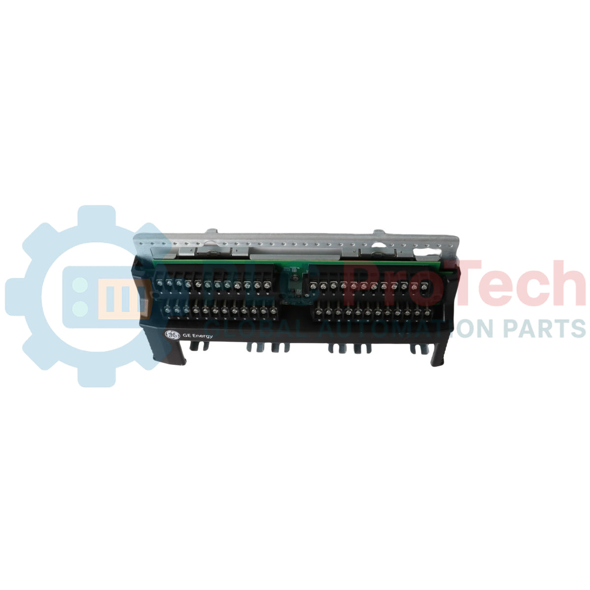
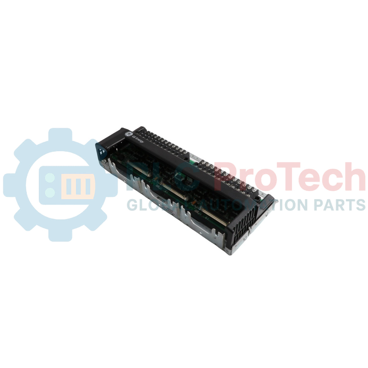
The IS200TBAIS1C (IS200TBAIS1C) is a mission-critical, high-integrity Analog Input Terminal Board custom-engineered by General Electric for the Mark VIeS functional safety and functional turbine protection framework. Functioning as the localized structural termination layer for safety-instrumented loops, this passive hardware card channels raw low-voltage analog sensor signals from the field directly into active processing networks. High-risk, continuous-process industries—including chemical separation matrices, combined-cycle power utilities, and LNG compression stations—rely on the IS200TBAIS1C (IS200TBAIS1C) to sustain real-time monitoring circuits. By featuring complete conformal PCB protection layers and certified compliance for hazardous location boundaries, this board isolates sensitive controller cores from high-voltage field faults, suppresses high-frequency induction noise, and prevents false safety trips that lead to facility downtime.
Technical Configuration & Infrastructure Features
The internal architecture, circuit layout, and signal processing parameters of the IS200TBAIS1C termination card guarantee steady automation tracking.
-
High-Density Analog Ingestion: Outfitted with dedicated terminal barrier strips engineered to accept multiple independent channels of millivolt, volt, or 4-20 mA current loop transmitter feeds concurrently.
-
HazLoc Environmental Certification: Fully validated under official GEH-6725 guidelines for safe mounting within certified Class I, Division 2 explosive boundaries and Zone 2 hazardous gas groups without arcing risks.
-
Conformal Insulation Protection: Coated with a uniform, factory-applied thin-film insulation chemical layer that seals copper paths against moisture tracking, marine salt spray, and airborne hydrogen sulfide corrosion.
-
Passive-to-Active Modular Marriage: Serves as the structural mounting foundation for active IS220 series analog I/O packs, utilizing integrated multi-pin connection headers to route conditioned logic telemetry.
Performance Specifications & Engineering Index
| System Parameter |
Factory Document Specification Standard |
| Model Designation |
IS200TBAIS1C |
| Brand Manufacturer |
GE Gas Power (General Electric Automation) |
| Control System Line |
Speedtronic Mark VIeS Safety Control Platform |
| Module Classification |
High-Density Analog Input Termination Board |
| Channel Signal Type |
4-20 mA current loops, Voltage inputs, Transducer loops |
| Cabinet Configuration |
Designed for Compact and Redundant Enclosures |
| Hazardous Location Rating |
Class I, Div 2, Groups A, B, C, D / Zone 2 IIC T4 |
| PCB Protective Barrier |
Comprehensive Conformal Coated Substrate |
| Physical Card Size |
Standard GE Terminal Board Profile (approx. 16 cm x 11 cm) |
| Operating Ambient Window |
-30 to +65 deg C Continuous Thermal Exposure |
| Storage Temperature Boundaries |
-40 to +85 deg C Maximum Extended Limits |
| Manufacturing Location |
United States (USA) |
Substation Engineering & Lifecycle FAQs
What specific field applications demand the deployment of the C-revision IS200TBAIS1C board over earlier updates?
The IS200TBAIS1C revision integrates enhanced component suppression networks and specific conformal coating standards validated under modern GEH-6725R safety guidelines. It is engineered specifically for functional safety loops in Mark VIeS configurations where continuous analog data—such as critical fuel valve positions or high-pressure steam telemetry—must remain uncorrupted during localized electrical surges.
Does this passive terminal board limit the thermal operating parameters of the attached active I/O packs?
According to official HazLoc temperature matrices, the passive board substrate handles a wide ambient thermal envelope from -30 to +65 deg C. However, field engineers must cross-verify the specific documentation for the attached active electronic packs (such as the IS220UCSAH1A or specific IS220PAIC blocks) as certain active processing components operate under tighter windows (e.g., 0 to 65 deg C) due to localized internal microchip power dissipation.
Can field wiring be landed onto the terminal blocks while the host control system remains energized?
To shield internal analog-to-digital converters and sensitive sensor loops from inductive transient damage or unexpected short-circuits during field installation, you must isolate signal loop power before terminating or disconnecting instrumentation lines from the screw blocks.
Field Engineering & Installation Protocol
-
Terminal Screw Torque and Terminal Landings:
When landing external shielded analog wires onto the barrier terminal blocks of the IS200TBAIS1C, strip back wire insulation by exactly 6 mm. Terminate the conductors into the screw clamps and apply a maximum tightening torque profile of 0.5 N-m (4.4 inch-lbs). Overtorquing can fracture the underlying solder pads, while loose connections will introduce signal resistance anomalies, degrading 4-20 mA reading accuracy under low-frequency turbine deck vibration.
-
Shield Grounding and Drain Wire Termination:
To maintain full compliance with the electromagnetic compatibility guidelines detailed in the Mark VIeS manual, all field instrumentation shield drain wires must be gathered and bonded cleanly to the designated cabinet earth grounding bar. Do not allow raw shield braids to contact adjacent signal traces on the board face, preventing ground loop offsets from corrupting localized differential analog logic.
-
Conformal Coating Care and Enclosure Clearance:
While the board features a G3 conformal coating shell to resist moisture and airborne corrosive gases within industrial areas, take absolute care during panel sliding actions to avoid scoring the substrate surface. Maintain a minimal free-air convection clearance gap of 4 cm around the board boundaries inside the enclosure housing to encourage passive heat dissipation, preventing local hotspots from reducing the lifespan of internal passive components.