Product Overview
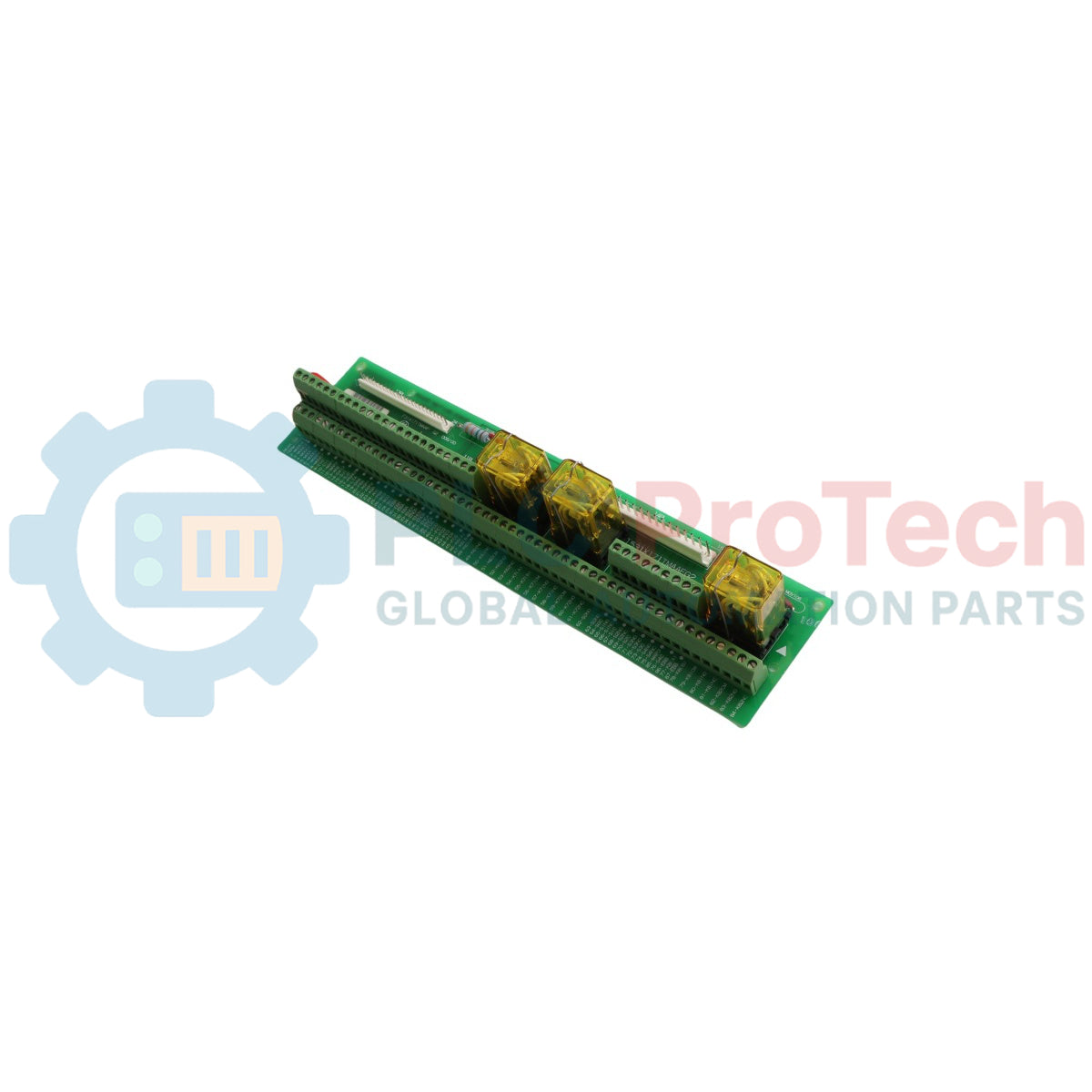
The 531X171TMAAFG2 is a specialized high-reliability Terminal Board Relay Card engineered by General Electric for the EX2000 digital excitation and drive ecosystem. Serving as a crucial centralized link for signal I/O routing and complex interface processing, this industrial board connects directly to the core drive logic card via specialized multi-conductor ribbon cables. High-demand industrial sectors—including deep-pit mining facilities, thermal power generation plants, and gas compression infrastructure—rely on this module to safely segregate digital control loops from field-side actuator currents. By establishing clean potential-free feedback connections, the card enables early anomaly identification, protects upstream control computing systems from inductive spikes, guarantees rapid field-device signaling, and minimizes costly plant downtime.
Circuitry Topography & Interface Protocols
The internal hardware configuration of the 531X171TMAAFG2 controller board focuses on reliable terminal grouping, signaling isolation, and cross-generation module substitution.
-
Potential-Free Contact Contacts: Outfitted with four high-integrity dry changeover relay paths designed to map essential equipment updates such as power failure alerts, generalized system alarms, battery low parameters, and active bypass status loops.
-
Dual Serial Integration Interface: Houses an integrated USB connector alongside a heavy-duty 9-pole Sub-D connector port, facilitating advanced processing communications between localized computing systems and backup power frameworks.
-
Drop-In Drop-In Replacement: Engineered with backward-compatible trace mapping, allowing this specific hardware revision to replace multiple legacy or damaged GE interface boards without dropping core system functional parameters.
-
Low-Power Actuation Network: Requires an operational current of only 8 to 18 V, drawing a maximum threshold of 2 W when all dry contact relays are driven simultaneously into closed configurations.
Performance Data & System Indexes
| System Parameter |
Engineering Specification |
| Model Designation |
531X171TMAAFG2 |
| Brand Manufacturer |
General Electric (GE) |
| Control Series Line |
EX2000 Excitation / Drive Platform |
| Module Identification Class |
Terminal Board Relay Card / I/O Interface |
| Operational Power Input |
8 to 18 VDC Range |
| Maximum Module Power Draw |
2 W maximum (with all relay channels closed) |
| Signal Input Activation Level |
2.4 VDC at 1.35 mA minimum active state threshold |
| Output Type Layout |
Electromechanical Relay Contacts via Screw Terminal Blocks |
| Maximum Contact Voltage Rating |
60 VDC or 42 VAC RMS Ceiling |
| Maximum Continuous Current |
1.25 A maximum (50 VA maximum inductive load ceiling) |
| Ambient Temperature Boundaries |
-10 to +40 deg C Operational Window |
| Storage Temperature Limits |
-40 to +60 deg C Maximum Thermal Cap |
| Country of Manufacture |
United States (USA) |
Functional Operations & Retrofitting FAQs
Can the 531X171TMAAFG2 direct-replace older generation terminal boards without changes to field wiring?
No, a straight drop-in replacement requires small field line updates as outlined in the GE technical manuals. For example, if your existing damaged card maps a wire to terminal 24 on the ACOM node, that field wire must be migrated to the AN1 terminal on the new board assembly. Furthermore, certain terminal routes require moving wires from the 4TB terminal block group over to the 3TB block group on the new layout.
What is the correct procedure if a signal input drops below 2.4 VDC during system testing?
An input voltage below 2.4 VDC or an input current dropping under 1.35 mA will fail to reliably trigger the on-board optocouplers or relay coils. Technicians must trace the signal source loop to clear high-resistance terminal connections or correct line voltage drops across long field cable runs.
What critical variables determine the maximum power rating handled by the relay outputs?
The integrated changeover relay contacts are strictly rated for low-voltage signal deployment up to a maximum ceiling of 60 VDC or 42 VAC RMS. The absolute continuous current cap is 1.25 A, provided the overall reactive power accumulation does not cross the 50 VA limit. Exceeding these values can weld contact points or trace circuits instantly.
Engineering & Installation Guide
-
Electrostatic Grounding and Component Protection:
The 531X171TMAAFG2 contains delicate solid-state components sensitive to static electricity. Keep the module sealed inside its anti-static shielding bag until the immediate moment of installation. Field staff must attach a grounded static wrist strap to an unpainted section of the enclosure chassis before handling the board, and handle the PCB strictly by its outer fiberglass borders to prevent skin oils and static charges from touching the components or exposed solder joints.
-
Retrofitting Terminals and Wire Relocation Rules:
When replacing a legacy board variant with the modern 531X171TMAAFG2 revision, verify terminal designations across the original prints. When adapting lines from old terminal 24, shift the lead from the ACOM terminal over to the AN1 position. Carefully relocate the wire groups landed at the legacy 4TB header directly onto the 3TB terminal block assembly to preserve correct logical signal cross-referencing.
-
Terminal Torque Limits and Insertion Controls:
Strip all field lines back by 7 mm and secure them into the heavy-duty screw blocks. Tighten all terminals to a maximum torque rating of 0.4 N-m (3.5 inch-lbs) using an insulated industrial screwdriver. Excess torque can fracture the internal trace links between the terminal block and the board layer, while under-torquing leads to open circuits under heavy vibration on industrial machinery decks.