System-Level Overview & Operational Value
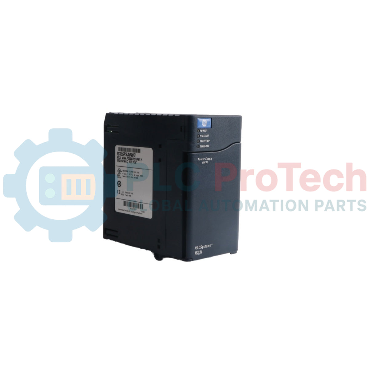
The IC695PSA040 (IC695PSA040) is a high-efficiency 40-Watt power supply module engineered for the GE PACSystems RX3i platform. Operating from universal input voltage ranges of 85 to 264 VAC or 100 to 300 VDC, this module supplies steady power distribution directly across the backplane to drive local processing and I/O assets. Industrial operations inside automated water treatment plants, chemical processing facilities, and manufacturing assembly lines rely on the IC695PSA040 (IC695PSA040) to secure predictable controller execution under fluctuating grid supply conditions. The power supply module isolates internal rack electronics from field electrical noise, logs predictive faults directly to the CPU tables during thermal or load stress, and maintains an integrated ride-through capability. This architectural resilience prevents sudden PLC drops, protects critical runtime parameters, and significantly cuts costly unplanned facility downtime.
Architectural Infrastructure & Internal Protection
The hardware topology of the IC695PSA040 module centers on localized triple-rail output management and automatic electronic protection.
-
Triple-Rail Voltage Output: Independently delivers +5.1 VDC and +3.3 VDC to satisfy RX3i system-level module demands, alongside a dedicated +24 VDC relay output path to power external output relay modules.
-
Active Overcurrent Controls: Features built-in electronic current limiting that caps the 5.1 VDC rail at 7 Amps and the 3.3 VDC rail at 10 Amps. Under overload or short-circuit faults, the supply shuts down automatically and initiates continuous auto-restart attempts until the underlying field fault is cleared.
-
Comprehensive Status Diagnostics: Hosts an array of four frontline LED status indictors coupled to internal diagnostic relays that broadcast real-time overtemperature, overload, and internal component health directly to the central CPU fault logger.
Performance Data & Hardware Matrix
| Engineering Index |
Technical Specification |
| Model Number |
IC695PSA040 |
| Brand Identifier |
GE PACSystems (General Electric) |
| Control System Series |
RX3i Controllers |
| Total Rated Output Power |
40 Watts maximum total |
| Nominal Input Rating |
120/240 VAC or 125 VDC |
| AC Input Range Range |
85 to 264 VAC |
| DC Input Range Range |
100 to 300 VDC |
| Maximum Input Power |
70 Watts maximum at full load |
| Inrush Current Threshold |
4 Amps for 250 milliseconds maximum |
| Current Output Specs |
5.1 VDC (0 to 6 Amps), 3.3 VDC (0 to 9 Amps), 24 VDC (0 to 1.6 Amps) |
| Voltage Boundaries |
5.1 VDC (5.0 to 5.2 VDC), 3.3 VDC (3.1 to 3.5 VDC), 24 VDC (19.2 to 28.8 VDC) |
| Galvanic Isolation |
250 VAC continuous (1500 VAC for 1 minute input to backplane) |
| Ride-Through Duration |
20 ms minimum during source interruption |
| Field Wiring Range |
14 AWG to 22 AWG single wire per terminal |
| Daisy-Chain Capacity |
Up to 4 PSA040 units |
| Operating Air Limits |
0 to 60 deg C (External Ambient) |
| ATEX Protection Code |
II 3 G Ex nA IIC T3C |
| Country of Origin |
United States |
Technical Diagnostics FAQs
Can the IC695PSA040 power supply be configured in a parallel arrangement to achieve N+1 redundancy?
No. This specific power supply is designed exclusively for solo operation within an RX3i Universal Backplane (IC695 catalog series). It cannot be paired with other power supplies to scale system capacity or provide hardware redundancy. Attempting to run older versions (version IC695PSA040C and earlier) alongside another supply inside the same backplane slot can cause severe equipment damage.
What causes the main Power LED indicator to turn from steady Green to Amber?
A Green light indicates that the module is powered up and successfully delivering stable DC rails to the backplane. An Amber light shows that input power is properly applied to the module's input wiring blocks, but the front-panel toggle switch is set to the OFF position, preventing power delivery to the rack.
What underlying systemic failures cause a hard shutdown without throwing an external LED fault indicator?
A non-repairable internal fusible link resides in the input line as a final hardware backup. While the module usually activates electronic shutdown before this fuse fails, an extreme internal component short-circuit or an excessive input overvoltage surge can open this link permanently. When this fuse blows, all operational indications cease, and the module requires physical replacement.
Field Engineering & Maintenance Protocol
-
Shock Hazard Mitigation & On/Off Control Safety:
During active runtime with an AC power source, dangerous voltages (120 VAC or 240 VAC) exist on the internal circuit structures of the module. The front terminal access door must remain closed during standard runtime to prevent fatal shock hazards. Note that the front ON/OFF toggle switch behind the door only controls the secondary DC output stages; it does NOT disconnect live incoming line power from the terminal blocks.
-
Wiring Insertion and Torque Limits:
Strip all terminal conductors to a minimum length of 9 mm to 11 mm. Ensure the wire is fully inserted into the terminal housing until the conductor insulation sits flush against the internal insulation stop. Tighten the screw clamps carefully, ensuring you do not exceed the maximum allowable torque limit of 0.5 N-m (4.4 inch-lbs). Improper insertion can cause the screw clamp to bind on the wire insulation, leading to open circuits or hot termination points.
-
Overvoltage Protection Jumper & Hi-Pot Testing Routine:
The bottom terminal blocks contain a Metal Oxide Varistor (MOV) surge circuit that must be connected to frame ground using a user-installed jumper for basic input overvoltage protection. To conduct a high-potential (Hi-pot) dielectric test on the supply, you must disable this overvoltage circuitry by removing this jumper. Reinstall the ground jumper immediately after testing is complete to restore transient protection.