Product Overview
The DS3800NPSE1E1G (DS3800NPSE1E1G) is a vital, high-reliability power regulation element engineered by General Electric within the classic Speedtronic Mark IV turbine control architecture. Operating as a dedicated internal power supply substrate, this printed circuit board conditions, stabilizes, and distributes raw internal DC voltages to support the critical processing cores and trip logic arrays of the turbine control system. Heavy industrial turbine facilities—including base-load thermal power plants, massive oil refining complexes, and offshore natural gas extraction platforms—rely on the DS3800NPSE1E1G (DS3800NPSE1E1G) to run continuous automation routines. By delivering clean, low-ripple voltage to sensitive upstream chips, the board guards against logic signal dropouts, suppresses hazardous transient surges, and prevents severe turbine forced outages or catastrophic overspeed scenarios.
Architectural Component Topography
The internal hardware topology, protection circuit footprints, and onboard adjustment matrices of the DS3800NPSE1E1G power substrate ensure rigorous line filtering and stable voltage regulation.
-
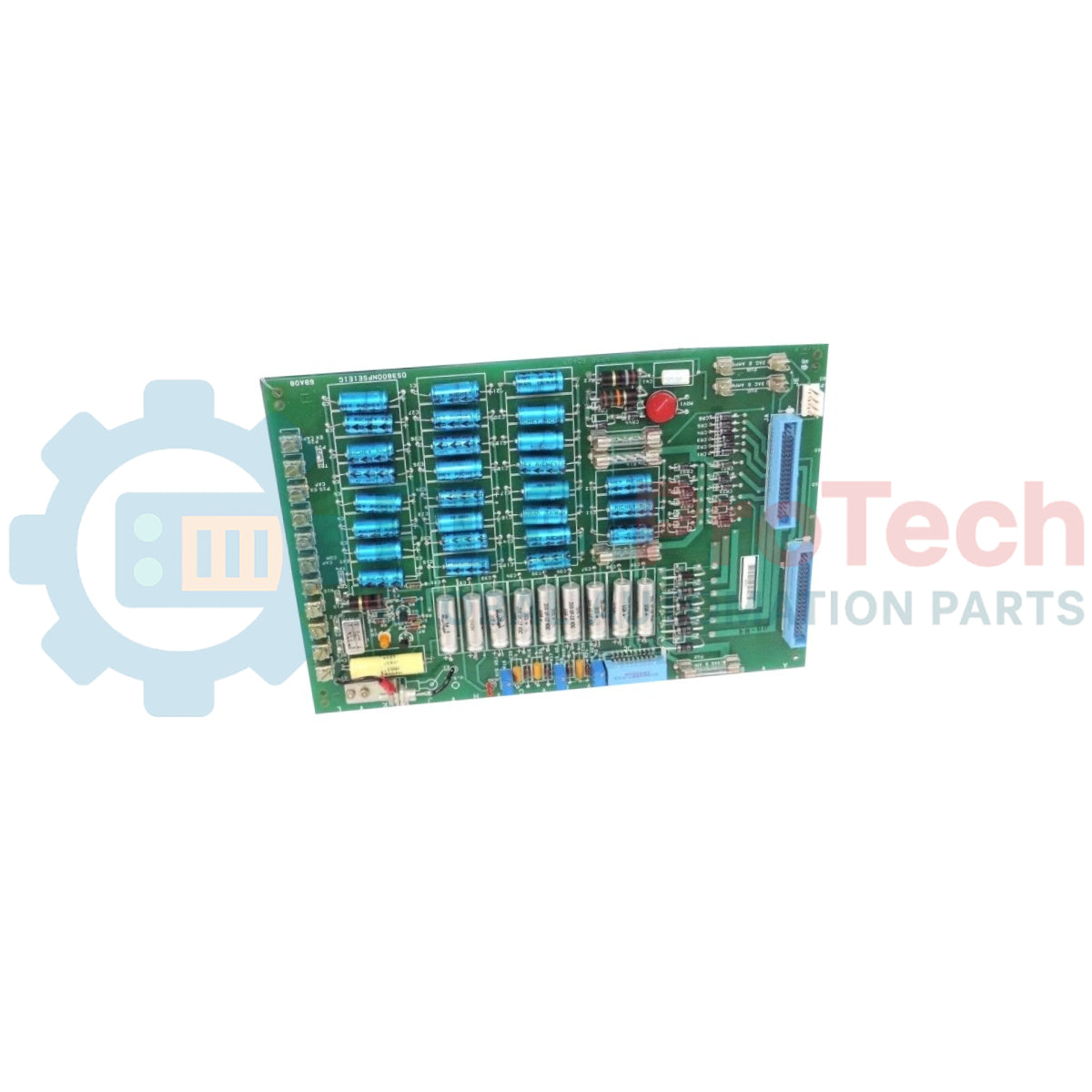
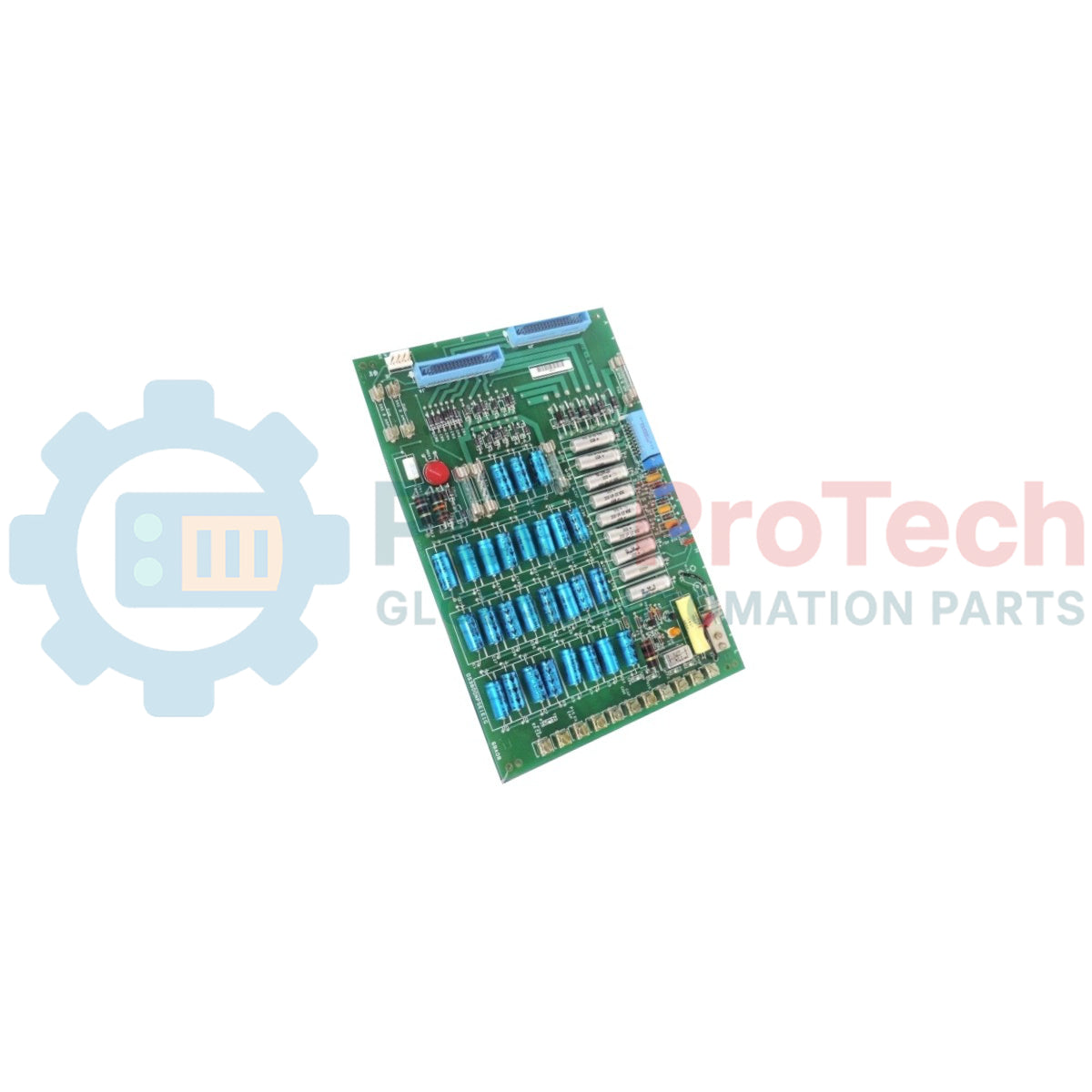
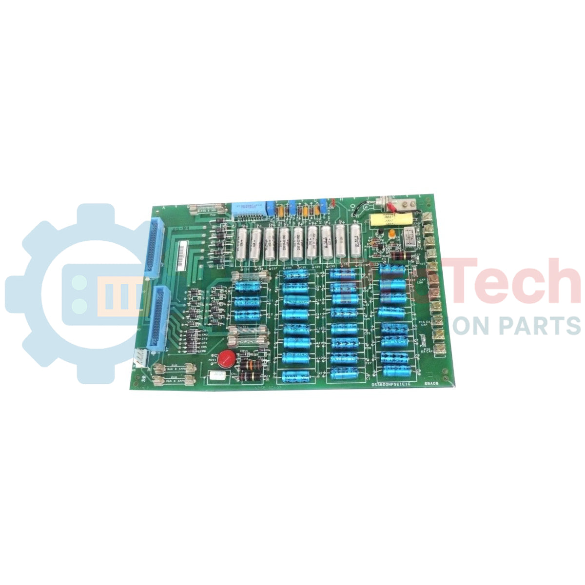
Vertical Interface Layout: Outfitted with two prominent, vertically aligned light blue male connector interfaces alongside a single, compact light blue sub-connector, ensuring reliable multi-bus data link integration.
-
High-Capacity Capacitive Filtering: Features twenty-seven medium-sized blue capacitive elements labeled C1 through C27 arranged in strict vertical rows, paired with nine silver capacitors labeled C31 through C39 in a horizontal alignment to flatten voltage ripples.
-
Onboard Overcurrent Protection: Outfitted with four functional onboard fuse blocks, plus two unpopulated, pre-drilled trace positions, allowing maintenance teams to adjust overcurrent safety margins based on specific panel loads.
-
Dynamic Voltage Calibration: Houses three precision potentiometers equipped with manually adjustable rotary dials, enabling precise calibration of output resistances and voltage regulation thresholds directly on the test bench.
-
Transient Suppression Matrix: Combines twenty-four small black-and-grey diodes arranged in precise vertical arrays with a heavy-duty Metal Oxide Varistor (MOV) at the bottom baseplate to ground steep inductive incoming voltage spikes.
Operational Parameters & Asset Metrics
| Hardware Parameter |
Certified Technical Specification Standard |
| Model Identity |
DS3800NPSE1E1G |
| Brand Manufacturer |
General Electric (GE Controls Group) |
| Control System Line |
Speedtronic Mark IV Turbine Control Platform |
| Module Classification |
Internal DC Power Supply Board Assembly |
| Interface Connections |
2 x Large Male Connectors, 1 x Small Connector (Light Blue) |
| Capacitor Layout Array |
27 x Vertical Blue (C1-C27) / 9 x Horizontal Silver (C31-C39) |
| Surge Suppression Block |
Integrated Bottom-Mounted Metal Oxide Varistor (MOV) |
| Voltage Tuning Mechanism |
3 x Precision Rotary Dial Potentiometers |
| Onboard Fusing Profile |
4 x Active Fuse Terminals (2 Optional Expansion Slots) |
| Mechanical Mounting Setup |
4 x Factory-Drilled Insulated Isolation Anchors |
| Operating Ambient Window |
0 to 60 deg C Continuous Operational Parameters |
| Storage Thermal Boundary |
-40 to +85 deg C Maximum Extended Limits |
| Manufacturing Origin |
United States (USA) |
Turbine Panel Life-Cycle & Diagnostic FAQs
Why does the DS3800NPSE1E1G layout feature such a high density of onboard diodes and capacitors?
The Mark IV turbine control system relies on steady, uninterrupted power. Over one-third of the DS3800NPSE1E1G circuit footprint is populated with high-grade blue capacitors and filtering diodes to create a multi-stage rectification and smoothing matrix. This dense array filters out harmonic distortions from surrounding machinery, preventing voltage ripples from corrupting critical speed sensing loops.
What is the purpose of the four factory-drilled, insulated holes on the corners of the board?
These precision-drilled locations are engineered to secure heavy isolation spacers. Because power supply boards generate heat and manage higher current densities than logical processing boards, these insulated mounting points structurally decouple the substrate from the metal chassis frame, preventing trace-to-chassis short-circuits and minimizing low-frequency structural panel vibrations.
Can individual blown fuses on the DS3800NPSE1E1G board be replaced while the turbine is running?
No. To prevent diagnostic errors, inductive arcing, or unexpected trips in the primary Mark IV controller, you must completely power down the specific power supply rack before inspecting or replacing any fuses or adjustments.
Field Engineering & Installation Protocol
-
Insulated Spacer Mounting and Chassis Isolation:
When installing the DS3800NPSE1E1G power board into the Mark IV enclosure bay, always use fresh, non-conductive nylon hex standoffs through the four factory-drilled mounting holes. Tighten mounting screws to a maximum torque profile of 0.5 N-m (4.4 inch-lbs). Failure to verify electrical isolation between the board's edge traces and the metal backplane panel can result in ground faults that damage upstream logic components.
-
Potentiometer Calibration and Voltage Verification:
Before returning an online channel to active service, use a calibrated digital multimeter to check outputs at the testing pins. Adjust the three dial potentiometers smoothly using an insulated ceramic adjustment tool. Setting values too quickly can introduce voltage jumps that create overvoltage alarms within the central Mark IV control panel.
-
Convection Thermal Clearances and Fuse Maintenance:
Power distribution boards generate steady thermal dissipation during operation. Maintain a minimal physical ventilation clearance gap of 5 cm around the board boundaries inside the rack housing to promote natural air convection. Ensure all active fuses are seated firmly in their designated brackets, and replace worn components only with original fast-acting industrial fuses of identical voltage and current ratings.