Product Overview
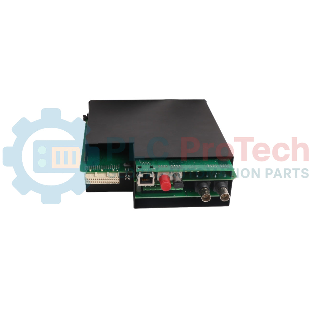
The UR-8GH (UR8GH) is a high-precision analog data acquisition interface engineered by General Electric for the UR Series (Universal Relays) network protection ecosystem. Functioning as a high-density primary scaling block, this critical card safely steps down high-capacity voltage and current dynamics from field instrument transformers into millivolt processing lines for the relay's arithmetic core. Power distribution infrastructures—including extra-high voltage transmission switchyards, automated hydroelectric stations, and heavy petrochemical processing facilities—rely on the UR-8GH (UR8GH) to capture sub-cycle line disturbances and voltage phase fluctuations. By providing 4 CT (Current Transformer) and 4 VT (Voltage Transformer) galvanically isolated input channels on a single substrate, this module ensures accurate real-time line calculation metrics, shortens breaker response profiles during high-current line faults, and minimizes plant unprogrammed downtime.
Technical Configuration & Sensor Interfacing
The advanced structural wiring matrix, channel segregation filters, and operational frequency boundaries of the UR-8GH measurement module govern its grid monitoring precision.
-
Dual-Source Parameter Ingestion: Features a balanced 4 CT and 4 VT channel grid configuration designed to track three-phase voltage and current lines simultaneously along with an independent neutral ground path.
-
Galvanic Protection Boundaries: Implements an advanced structural isolation barrier between the terminal connection block and the internal processing backplane, preventing severe inductive fault spikes from damaging the core CPU processor.
-
Sub-Sample Phase Synchronization: Operates in perfect synchronization with the Universal Relay backplane logic, ensuring zero phase-angle skewing between corresponding current and voltage waveform samplings.
-
Dynamic Grid Mapping Matrix: Transmits high-fidelity analog values to the host system firmware to support complex protective logic paths, including distance protection (21), directional overcurrent (67), and synchronized line monitoring telemetry.
Technical Specifications
| Protection Metric |
Factory System Specification Standard |
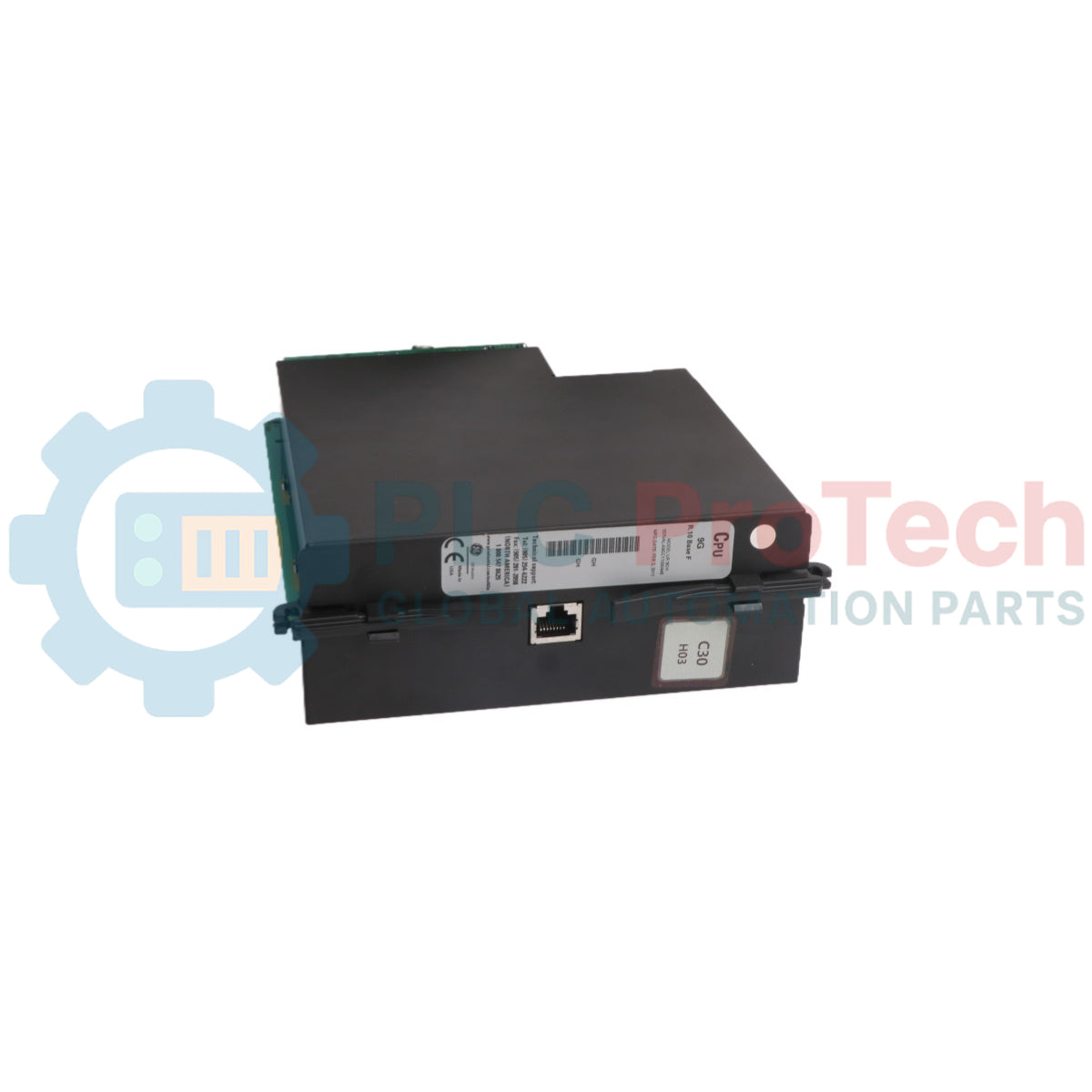
| Model Designation |
UR-8GH |
| Brand Manufacturer |
GE Multilin (General Electric Grid Solutions) |
| Control System Line |
UR Series Universal Relays Platform |
| Module Classification |
4 CT / 4 VT Standard Analog Input Module |
| Current Inputs (CT) |
4 Isolated Channels with high continuous thermal bounds |
| Voltage Inputs (VT) |
4 Isolated Channels optimized for instrumentation lines |
| Frequency Tracking Bounds |
50 Hz / 60 Hz Nominal Grid Compatibility |
| Data Log Resolution |
High-speed multi-sampling analog-to-digital matrix |
| Configuration Software |
EnerVista UR Configuration Utility Platform |
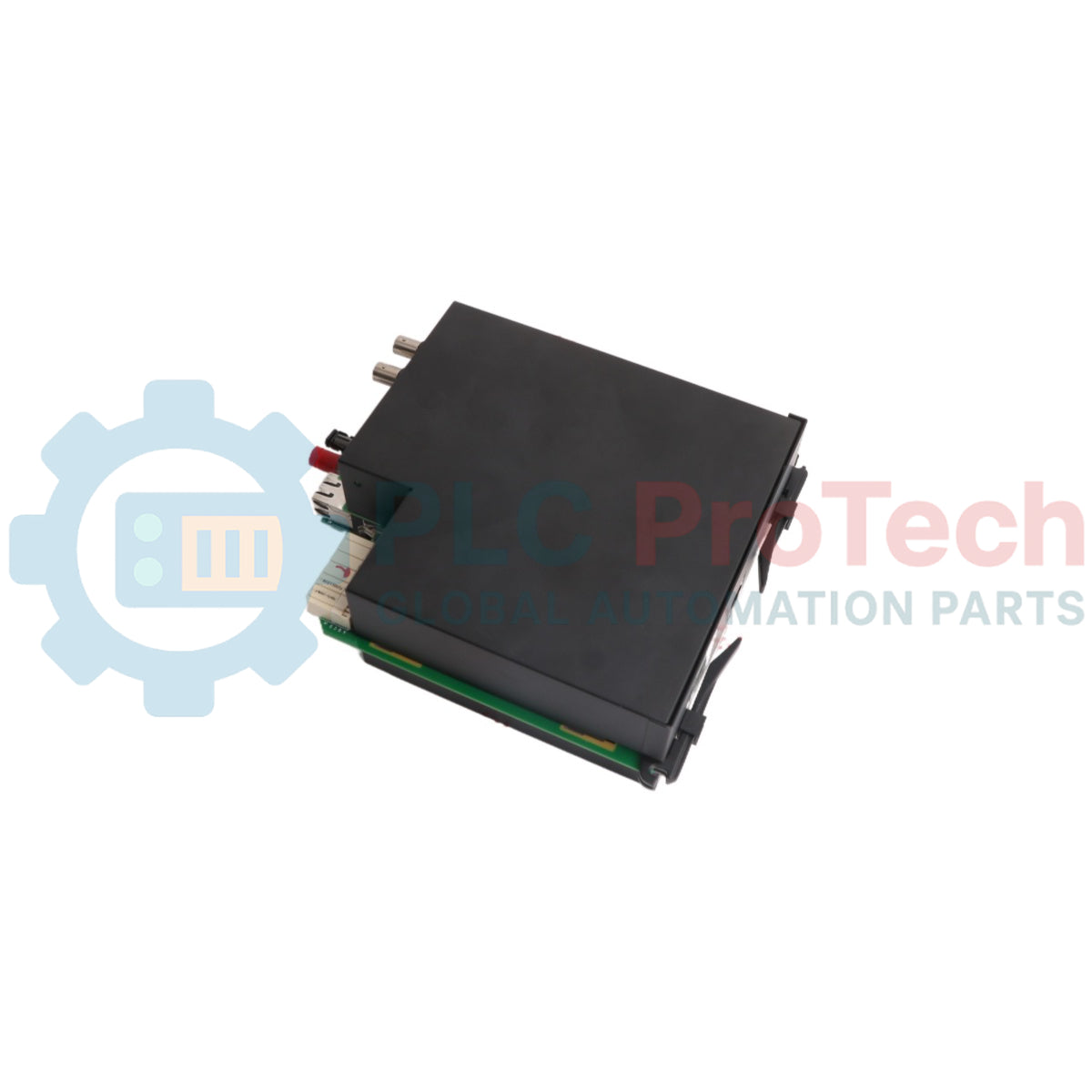
| Physical Dimensions |
Standard UR Expansion Slot Case (approx. 15 cm x 18 cm x 4 cm) |
| Hardware Shipping Weight |
1.35 kg |
| Operating Temperature Window |
-40 to +60 deg C Continuous Environmental Range |
| Manufacturing Location |
Markham, Ontario, Canada |
Protection System & Diagnostic FAQs
How do system engineers verify individual CT/VT calibration or troubleshoot open-circuit metrics on the UR-8GH?
Live analog vector measurements can be evaluated passively via the front LCD panel of the Universal Relay chassis or diagnosed directly through the EnerVista UR software workspace. This programming environment displays real-time current magnitude graphs, phase angles, and harmonic wave distortions, allowing immediate diagnosis of current transformer phase reversals or ungrounded neutral lines.
What are the consequences of an unprogrammed open-circuit fault crossing an active UR-8GH current transformer channel?
An open-circuit condition on an active CT secondary loop generates dangerous high-voltage transients across the terminal block pins, posing a lethal shock hazard to personnel and causing dielectric breakdown within the module's input circuitry. Technicians must ensure that shorting blocks are securely engaged prior to disconnecting any current line terminal screws.
Can the UR-8GH module be swapped or inserted while the utility automation panel remains live?
No. To prevent lethal induced voltages from open CT lines, accidental tripping of live substation breakers, or damage to the internal backplane microprocessor from electrical arcs, you must completely isolate all power and current transformer sources from the relay enclosure before extracting or seating any module.
Field Engineering & Installation Protocol
-
Terminal Screw Landing Constraints and Torque Specifications:
When landing heavy instrument transformer leads onto the terminal block of the UR-8GH, utilize high-integrity ring terminals to prevent wire pullouts. Insert wire links cleanly and tighten terminal screws to an exact torque profile of 1.4 N-m (12.4 inch-lbs). Loose current terminal connections cause resistive heating and can induce high-voltage arcing that destroys the underlying PCB solder points.
-
Twisted-Pair Shielding and Noise Suppression Guidelines:
Route all sensitive analog current and voltage transformer secondary circuits through dedicated, shielded twisted-pair instrumentation lines. Ground the cable shields at a single point inside the relay panel enclosure only. This installation rule blocks high-frequency electromagnetic noise generated by adjacent high-voltage circuit breakers from distorting the relay's phase-angle measurements.
-
Module Insertion Security and Grounding Path Integrity:
Carefully slide the UR-8GH board into its designated panel slot using the built-in plastic guide rails to protect the rear multi-pin pinout from alignment damage. Push the module home until its metal faceplate sits completely flush against the chassis housing, and tighten all exterior retention screws to a maximum torque profile of 0.6 N-m (5.3 inch-lbs). This structural connection establishes a low-resistance earth ground path to protect the internal data acquisition components from heavy substation electromagnetic interference (EMI).