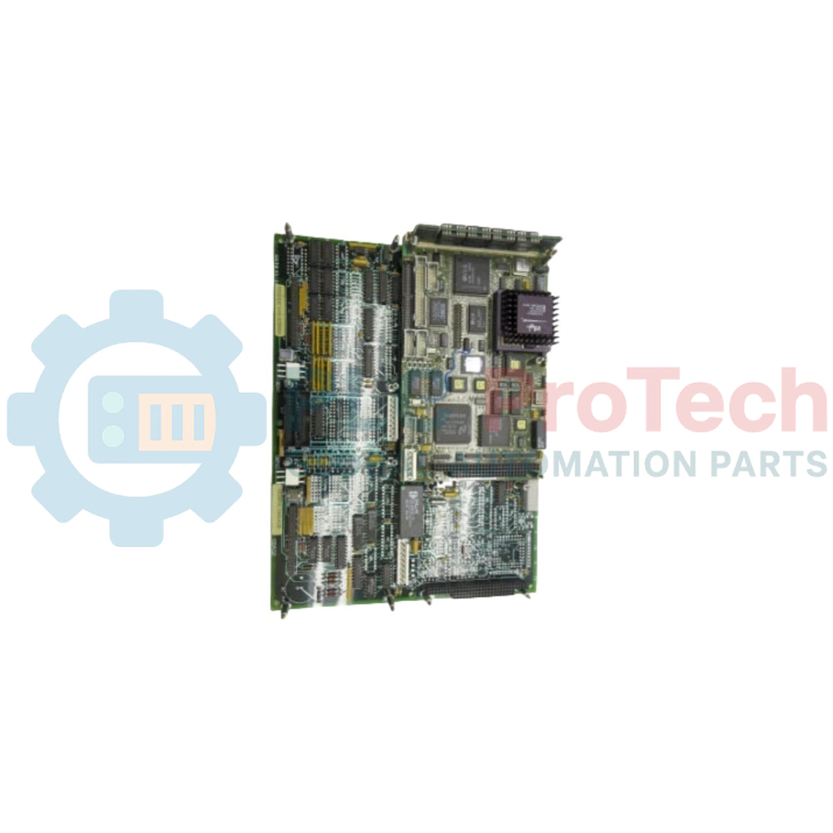
Product Overview
The DS215UCIAG1AZZ05A (DS215UCIAG1AZZ05A) is a high-reliability, microprocessed main control substrate engineered by General Electric for the landmark Speedtronic Mark V turbine control system line. Serving as the primary UC2000 Motherboard architecture, this specialized board executes demanding real-time regulation algorithms, manages critical communication paths, and processes sensor feedback to govern heavy industrial drive assemblies. Heavy continuous-process facilities—such as utility gas turbine generation plants, steam-driven manufacturing lines, and large-scale automated wind turbine farms—rely on the DS215UCIAG1AZZ05A (DS215UCIAG1AZZ05A) to supervise volatile operational boundaries. By integrating advanced core computing capabilities with an A-rated functional revision and specialized firmware options, the substrate minimizes data latency, dampens control system jitter, and guards high-value turbine assets against unprogrammed plant downtime or dangerous trips.
Model Suffix Breakdown
The structural variations, functional adaptations, and internal firmware configurations of the DS215UCIAG1AZZ05A motherboard assembly can be comprehensively decoded from its alphanumeric catalog number.
-
DS215 Functional Prefix: Identifies the domestic original manufacturing origin (General Electric factory plant in Salem, Virginia, USA) and designates this board as a specific Mark V Series special assembly version.
-
UCIA Product Acronym: Represents the official functional technical abbreviation for the primary UC2000 Motherboard architecture.
-
G1 Group Classification: Indicates the group one specific hardware configuration and terminal arrangement within the Mark V system matrix.
-
A Revision Parameter: Reflects the factory-integrated, A-rated functional product revision that enhances original baseline board layout specifications.
-
ZZ05A Suffix Token: Defines the implementation of a dedicated factory-loaded optional firmware package that modifies baseline runtime logic and diagnostic execution boundaries.
Asset Architecture & Performance Specifications
| Core Hardware Metric |
Certified Industrial Control System Standard |
| Model Identity |
DS215UCIAG1AZZ05A |
| Brand Manufacturer |
General Electric (GE Power & Controls Division) |
| Control System Line |
Speedtronic Mark V Turbine Control Series |
| Functional Description |
UC2000 Main Processor Motherboard Unit |
| Onboard Processing Unit |
1 x High-Performance Industrial Microprocessor Core |
| Memory Architecture |
Multiple Programmable Read-Only Memory (PROM) Modules |
| Daughter Card Capacity |
1 x Dedicated Onboard Modular Daughterboard Interface Connector |
| Interface Port Density |
2 x 50-Pin Main Multi-Bus Ribbon Cable Connectors |
| Localized Telemetry |
1 x Integrated Horizontal Block of 10 Diagnostic Health LEDs |
| PCB Shielding Layer |
Standard Protective Conformal Coating Shell |
| Manufacturing Origin |
Salem, Virginia, United States (USA) |
| Operating Ambient Window |
0 to 60 deg C Baseplate Ambient Thermal Envelope |
| Storage Temperature Bounds |
-40 to +85 deg C Maximum Cabinet Storage Limits |
Operational Logic & Diagnostic FAQs
What is the functional difference between the DS215UCIAG1AZZ05A board and its parent model?
The baseline parent motherboard is the legacy DS215UCIAG1 PCB. The DS215UCIAG1AZZ05A model is a specialized evolution containing an A-rated functional layout optimization, structural standoffs for daughterboard expansion, and the factory-embedded ZZ05A optional firmware package, which provides modified processing capabilities for complex turbine profiles.
How do panel operators read the embedded block of 10 diagnostic LEDs during turbine runtime?
The onboard LED block provides continuous hardware health status visible while the drive is operating. Under normal processing operations, the lights flash sequentially from left to right. If the microprocessor detects a system fault or communication failure, the sequential scanning ceases, and the LEDs flash in a specific coded pattern to transmit an internal error code for rapid fault location.
Why does this specific motherboard require more physical depth inside the Mark V control enclosure?
The board features integrated structural standoffs and a modular plug connector designed to host a daughter card expansion. Selecting a daughter board adds advanced site-specific telemetry options, but the combined assembly increases the total mechanical width profile. System engineers must verify physical slot clearance inside the card rack prior to online replacement.
Engineering & Installation Guide
-
Electrostatic Grounding and Component Handling Rules:
The high-performance microprocessor core and adjacent PROM modules on the DS215UCIAG1AZZ05A are highly sensitive to electrostatic discharge (ESD). Field technicians must wear a properly bonded grounding wrist strap before pulling the card from its anti-static shielding package. Hold the board exclusively by its outer fiberglass edges, and avoid direct contact with the pin traces or conductive components to prevent latent circuit failure.
-
Daughterboard Alignment and Mechanical Fastening:
When joining a compatible daughter card to the motherboard, align its edge pins carefully with the main modular-type interface receptacle. Press down evenly until the connector is seated completely to ensure solid signal and power paths. Fasten the board securement screws into the matching chassis standoffs using a torque profile of 0.45 N-m (4.0 inch-lbs) to prevent connection shifts under low-frequency turbine cabinet vibrations.
-
Ribbon Cable Seating and Enclosure Replacement Tracking:
When connecting the dual 50-pin ribbon interfaces, verify that the locking ears on the sides of the headers snap inward completely to lock the connection. Route all internal wiring bundles smoothly to maintain unrestricted airflow. As a best practice for thermal management, always mount the new motherboard assembly into the exact rack position as the replaced board to maintain engineered passive convection paths inside the Mark V panel.