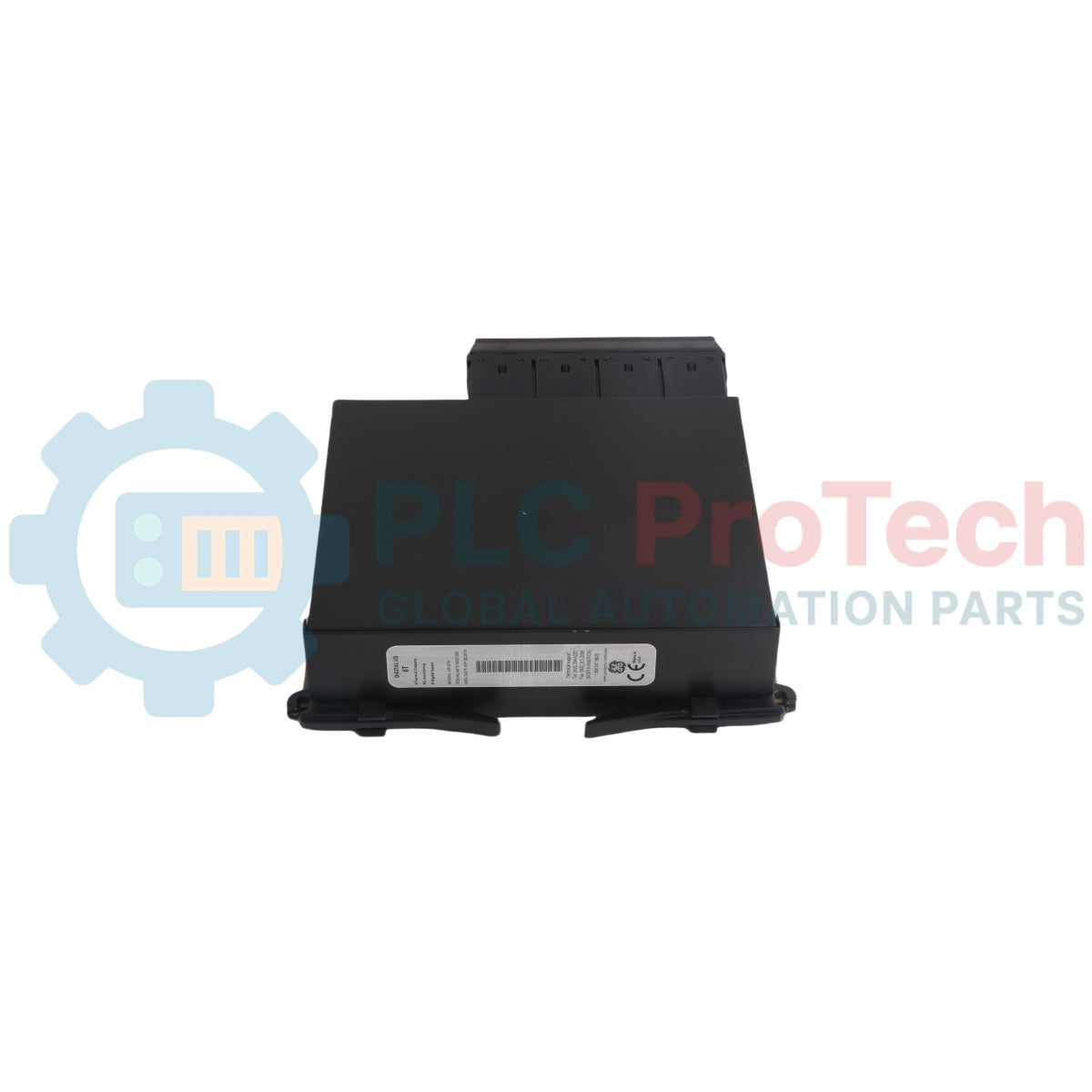
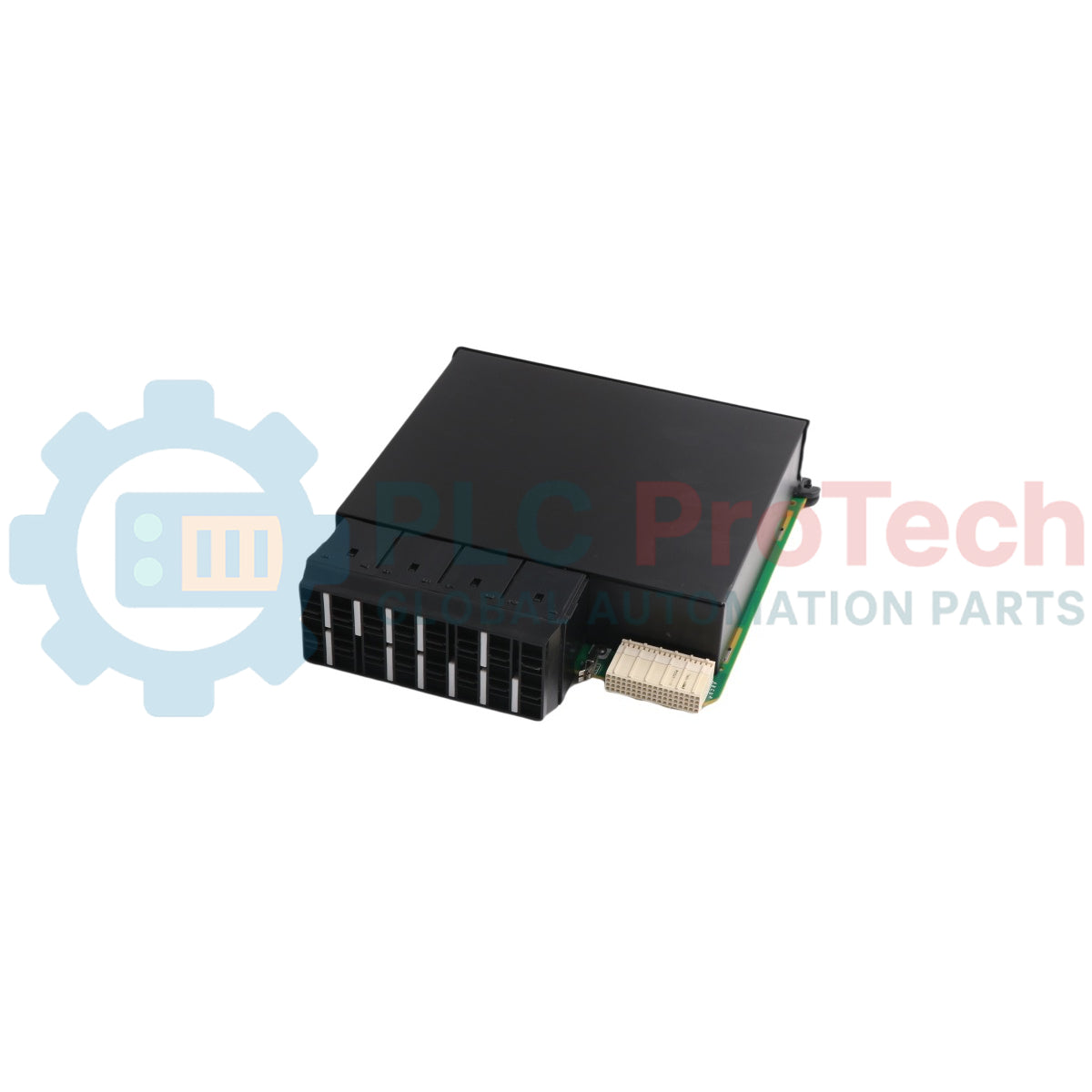
The UR-6TH (UR6TH) functions as a high-density Digital Input/Output Module engineered for the GE Vernova Multilin Universal Relay (UR) platform series. This hardware expansion block integrates directly into standard modular UR chassis frameworks—such as the F60, L90, G60, and B30 protective relays—to execute rapid interlocking logic and telemetry distribution across electrical substations and heavy industrial energy systems. It features an onboard combination of 8 contact inputs and 4 Form-A outputs specifically optimized to drive high-speed control commands.
The Form-A digital outputs operate without internal contact monitoring, utilizing advanced mechanical design to achieve a response duration of less than 4 ms. This ultra-fast switching profile makes the hardware highly appropriate for deployment inside master circuit breaker trip circuits where immediate arc interruption and protection sequence execution are mandatory. Operating within the host relay's native firmware architecture, the localized input and output paths are managed dynamically over internal backplane links via EnerVista UR Setup Software to automate sequence mapping and minimize physical auxiliary control panel wiring footprints.
Features
High-Speed Form-A Outputs: Equipped with 4 non-monitored Form-A contacts achieving an ultra-fast response speed of under 4 ms for direct breaker tripping applications.
Dense Contact Acquisition: Features 8 independent contact inputs to capture discrete status changes from auxiliary power equipment.
FlexLogic Programming Integration: Fully maps all 8 inputs and 4 outputs into the internal FlexLogic editor for tailored automation, automated overcurrent tripping, and external blocking schemes.
Hardwired Reduction Layout: Significantly decreases complex secondary hardwiring infrastructures inside traditional substation panel bays through localized digital point concentration.
Flexible Voltage Compatibility: Supports standard industrial DC control voltages spanning from 24V DC up to 250V DC depending on the definitive system configuration.
Applications
High-speed circuit breaker direct tripping (Trip) circuits.
Automated substation equipment interlocking and signaling networks.
Digital input/output point expansions for Multilin UR Series relays (F60, L90, G60, B30).
Distributed industrial power management systems requiring custom logic mapping.
Technical Specifications
Parameter
Specification & Technical Details
Manufacturer
GE Vernova (Grid Solutions / Multilin)
Model
UR-6TH
Module Type
Digital Input/Output Module (Digital I/O Module)
Product Family
Multilin Universal Relay (UR) Series
Input Channels
8 Contact Inputs
Output Channels
4 Form-A Outputs (No Monitoring)
Output Response Speed
< 4 ms (Ultra-high-speed response)
Rated Control Voltage
24V DC to 250V DC (Dependent on ordering code & configuration)
Configuration Tool
EnerVista UR Setup Software
Net Weight
Approx. 2 lbs 9 oz (1.16 kg)
Dimensions (H x W x L)
Approx. 1.5 in x 6 in x 7 in (3.8 x 15.2 x 17.8 cm)
Installation Guidelines
Hardware Compatibility Verification
When replacing or upgrading modular cards within an active relay system, ensure the new I/O module matching specifications align completely with the host relay's CPU generation and chassis type. Universal Relay I/O cards vary severely in feature layouts, such as the inclusion or omission of contact monitoring. Always compare the full alphanumeric ordering code printed on the primary relay nameplate and verify the targeted physical card slot (typically slots G, H, M, N, P, U, or W) before seating the hardware.
Pre-Installation Power Isolation
Completely disconnect the main secondary AC/DC auxiliary power supply feeding the Universal Relay host unit.
Isolate or mechanically lock out all external current, voltage, and circuit breaker trip loops terminating at the external field terminal blocks to avoid accidental field breaker deployment during the swap procedure.
Securely attach an electrostatic discharge (ESD) wrist strap and connect it to a verified physical earth ground to protect internal microprocessors from static electricity degradation.
Extracting the Defunct Module
Connect a PC to the relay and execute a full parameter backup via the EnerVista UR software, saving the current configuration as a .urs file.
Loosen the physical faceplate retaining fasteners situated at the top and bottom exterior corners of the target I/O slot frame using an appropriate screwdriver.
Grip the integrated black extraction handles firmly and pull the module outward along a straight, uniform path to disengage the board from the rear backplane bus assembly.
Inserting the New UR-6TH Module
Position the vertical side edges of the new UR-6TH circuit card inside the molded plastic guide tracks of the empty chassis slot.
Slide the module into the empty slot cavity smoothly until the outer front faceplate fits flush against the adjacent structural modules.
Apply firm, centered horizontal pressure on the faceplate borders to make sure the multi-pin rear connector seats completely into the backplane plug.
Tighten both the upper and lower panel retention screws to provide mechanical stability and complete the mandatory chassis grounding loop.
Post-Installation Commissioning
Reapply the system auxiliary power distribution to the primary power module of the relay chassis.
Monitor the automated self-test routine via the liquid crystal faceplate screen; confirm that no HARDWARE MISMATCH alerts or critical slot fault flags become active.
Connect via the EnerVista software suite, navigate to Status -> Hardware Configuration, and verify that the system correctly enumerates the new UR-6TH hardware block before restoring live operation to external I/O trip loops.
FAQ
What specific type of switching contacts are provided on the output channels?
The module contains 4 Form-A outputs which are Single Pole-Single Throw Normally Open (SPST-NO) contacts. These outputs are engineered without internal current or voltage monitoring components to maximize switching speed and minimize response delays under 4 ms, rendering them excellent for raw breaker trip routing.
Can this module be positioned in any slot within the Universal Relay frame?
No, this module must be positioned specifically in standard designated digital I/O slot spaces. These correspond to slots G, H, M, N, P, U, or W within the standard Universal Relay chassis architecture, depending on how your specific primary configuration code is assigned.
What occurs if the hardware generation of the module does not match the host relay frame?
If a hardware generation conflict happens between the newly inserted card and the legacy CPU or backplane firmware, the front faceplate of the Universal Relay will trip a critical fault indicator and throw a HARDWARE MISMATCH state, locking out operational software execution until the modules are unified.
Maintenance data connects work orders, sensor signals, asset history, costs, and technician knowledge. Used well, it improves planning, reliability, predictive maintenance, spare-parts control, and...
This article explains how integrated electric actuators, such as SMC’s e-Actuator series, are transforming industrial motion control by replacing traditional pneumatic and hydraulic systems. It...
This article explains how PLC systems perform core mathematical operations such as addition, subtraction, multiplication, division, modulo, and exponentiation within industrial automation. It shows...
The article explains several advanced Boolean logic functions used in PLC programming beyond basic AND, OR, and NOT operations. It covers how tools like truth tables, multiplexers, pulse generators,...
Boolean logic is the foundation of every PLC program. From simple machine controls to complex industrial automation systems, logic gates determine how controllers respond to changing inputs and...
Industrial firewalls play a critical role in OT cybersecurity, protecting PLC, DCS, and SCADA networks through segmentation, ingress/egress control, and IDS/IPS integration aligned with IEC 62443...
Choosing a selection results in a full page refresh.