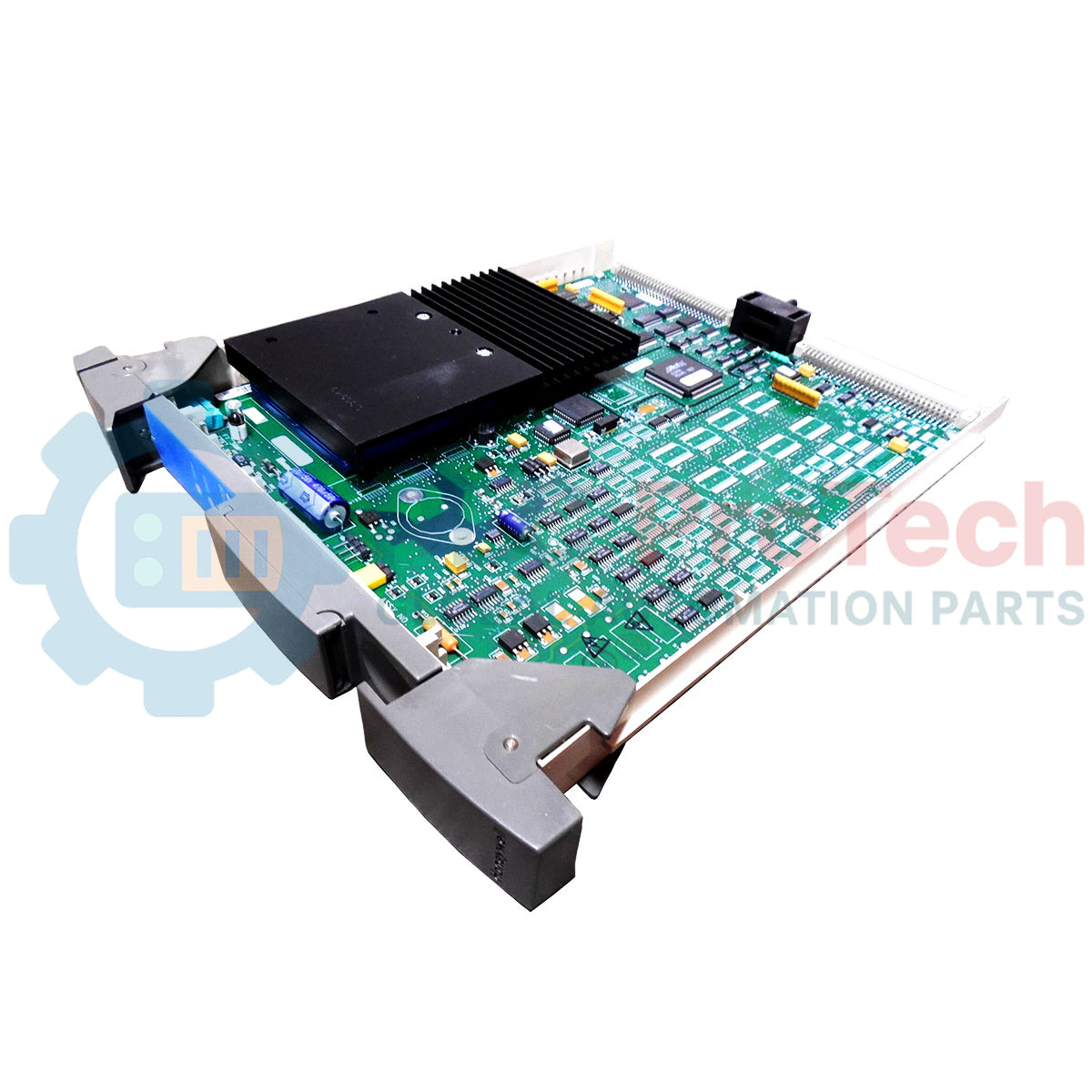
Description
Engineered for high-integrity safety instrumented systems, the Honeywell 10201/2/1 functions as an eight-channel fail-safe digital output module designed to drive resistive and inductive loads up to 13 W. Operating under the 11501 model architecture, this module provides 24 Vdc solid-state source outputs with integral short-circuit protection. To ensure flawless operation with inductive loads like solenoids, each of the eight channels features an integrated suppression diode. The module undergoes exhaustive automated testing diagnostics—including tests for de-energization capability, group de-energization via secondary means, output crosstalk, and diode performance—making it fully compliant with stringent fail-safe standards.
Features
-
8 Fail-Safe Channels: Provides 24 Vdc solid-state, short-circuit-proof source outputs.
-
Integrated Suppression Diodes: Built-in protective diodes on each channel handle inductive back-EMF without external components.
-
Comprehensive Safety Testing: Continuous background diagnostics verify output de-energization, secondary group isolation, crosstalk, and diode integrity.
-
Physical Key Coding: Features dual mechanical code holes (A9, C9) matching rack pins to prevent accidental insertion of incorrect module types.
-
Low Signal Degradation: Limits voltage drop to less than 2.0 Vdc at 500 mA, with minimal off-state leakage current under 0.1 mA.
Applications
- Emergency Shutdown (ESD) Systems
- Burner Management Systems (BMS)
- Fire and Gas (F&G) Detection Networks
- High-Integrity Pressure Protection Systems (HIPPS)
Technical Specifications
| Parameter |
Specification Value |
| Manufacturer |
Honeywell |
| Model Number / Article Number |
10201/2/1 |
| Model Type |
11501 |
| Number of Output Channels |
8 |
| Output Voltage (Nominal) |
24 Vdc (solid-state source) |
| Maximum Current per Channel |
550 mA |
| Maximum Lamp Load |
120 mA (2.9 W) |
| Maximum Load Capacitance |
1 uF |
| Voltage Drop |
< 2.0 Vdc at 500 mA |
| Off-State Current Leakage |
< 0.1 mA |
| Watchdog (WDG) Input Current |
8 mA |
| Internal Power Consumption |
5 Vdc at 25 mA / 24 Vdc at 25 mA |
| External Power Consumption |
24 Vdc at 70 mA (excluding output load) |
| Space Requirements |
4 TE, 3 HE (4 HP, 3U) |
| Module Coding Holes |
A9, C9 |
| Rack Coding Pins |
Large pins A9, C9 |
| Required Software Version |
Version 3.00 or higher |
| Certifications and Approvals |
CE, TUV, UL |
| Dimensions (H x W x D) |
3 cm x 20 cm x 15 cm (1" x 8" x 6") |
| Net Weight |
0.15 kg |
| Shipping Weight (Calculated) |
2.00 kg |
Empirical Engineering Insights
Alternative Models & Compatibility
The 10201/2/1 module requires safety runtime software version 3.00 or higher. For facilities migrating from legacy FSC architectures, ensure the host backplane's mechanical indexing matches the A9 and C9 physical key configuration. Failure to verify physical coding can damage backplane connector pins during blind insertion.
Application Pitfalls & Engineering Notes
While rated for a maximum load capacitance of 1 uF, highly distributed field cable runs can approach this threshold. Exceeding 1 uF can lead to transient inrush currents that the solid-state switch registers as an overcurrent fault, triggering a diagnostic shutdown. Always verify the lumped capacitance of your field cabling in critical ESD loops.
Commissioning & Wiring Tips
Ensure that the 24 Vdc external power supply driving the output channels is clean and isolated. Inductive suppression is handled internally, but running field cables parallel to high-voltage AC lines without proper shielding can couple noise into the watchdog circuit, resulting in diagnostic faults. Ground the cable shields at the cabinet entry point only.
Installation Guidelines
CRITICAL WARNING
Before installing or extracting this module, fully de-energize the rack and bleed any residual system charges. Hot-swapping without executing loop-bypass protocols on active safety loops may result in unintended process shutdowns or false trip conditions.
1
Inspect the module backplane connection and verify that the coding holes at A9 and C9 are clean and free of obstruction.
2
Slide the module gently into the designated slot along the guide rails until the rear Eurocard connectors sit flush against the backplane.
3
Secure the module to the rack chassis using the integrated front panel screws to ensure solid ground continuity.