Designing H-Bridge Motor Drives Without Shoot-Through
A practical guide to H-bridge motor drives covering switching states, dead time, inductive current paths, PWM choices, protection, PCB layout, PLC interfacing, and staged commissioning tests.
Manufacturer: Lenze
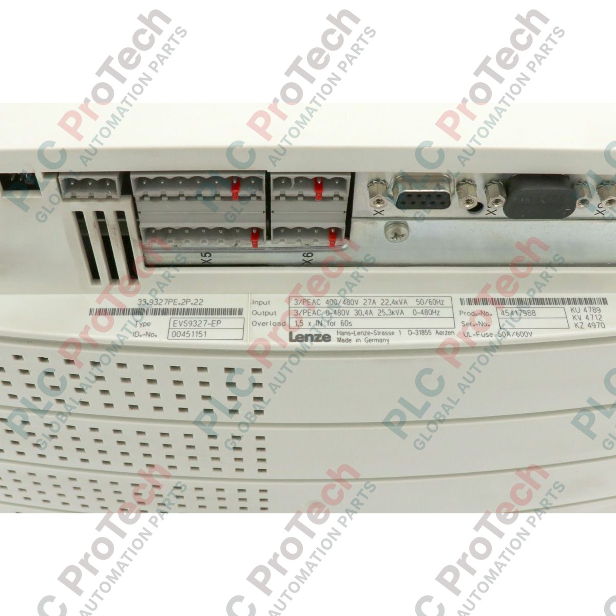
Product No.: EVS9327-EP
Country of origin:Germany
Product Type: Servo Drives
Barcode: 85044095
Payment: T/T, Western Union
Weight: 12500g
Dimensions: 35.00 x 25.00 x 25.00 cm
Shipping port: Xiamen
Warranty: 12 months
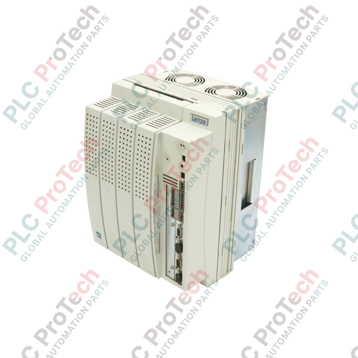
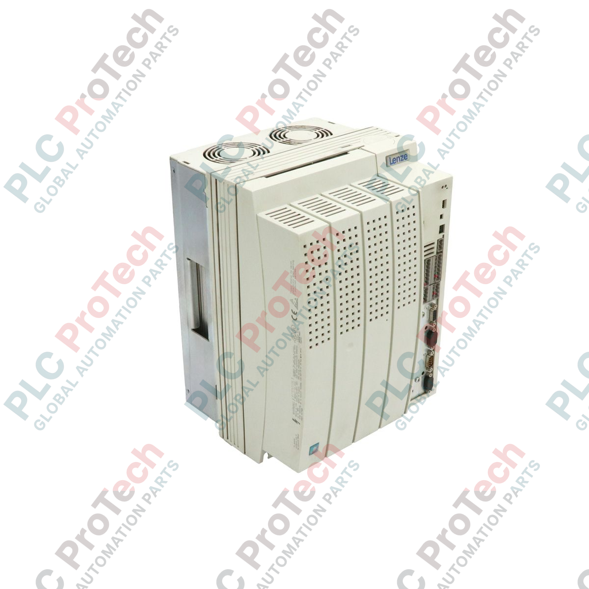
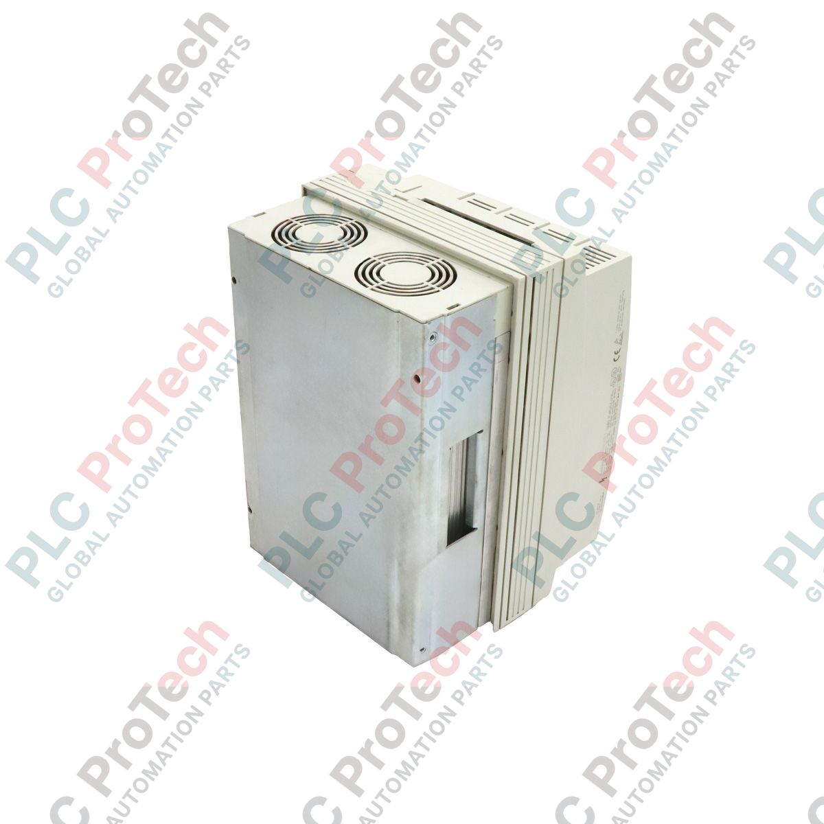
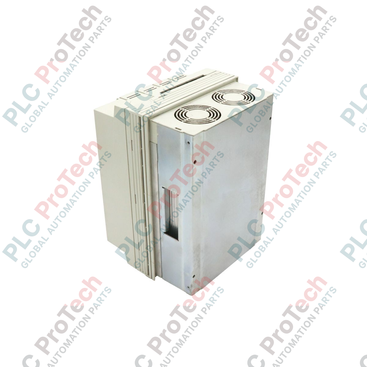
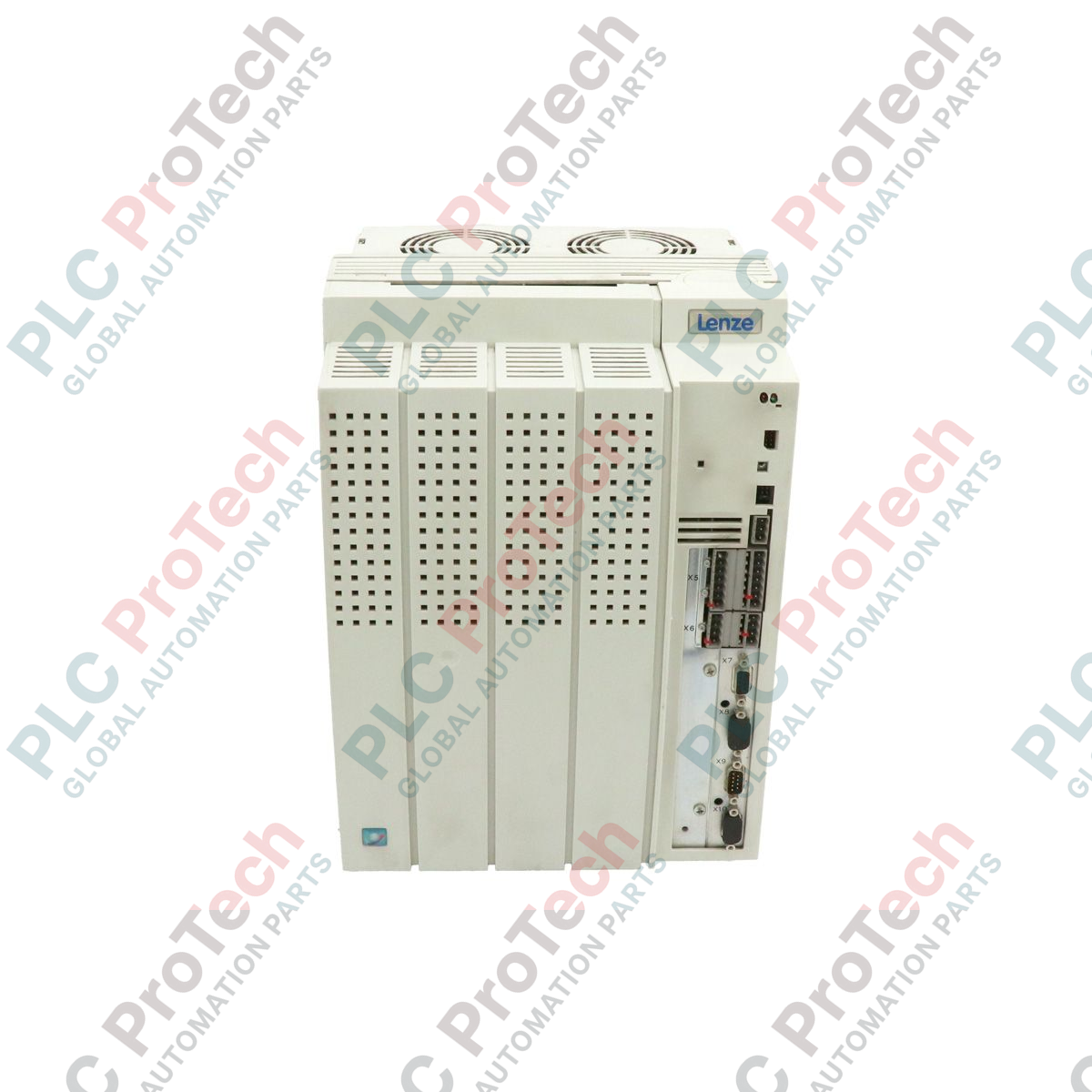
Managing complex motion profiles in high-performance industrial environments, the Lenze EVS9327-EP serves as a high-precision servo position controller within the legacy 9300-Series ecosystem. This robust drive is engineered to deliver precise speed, torque, and position control for demanding electrical and mechanical automation architectures.
| Parameter | Value |
|---|---|
| Manufacturer | Lenze |
| Model Number | EVS9327-EP |
| Product Series | 9300-Series |
| Device Type | Servo Position Controller |
| Rated Power Output | 15.0 kW |
| Enclosure Rating | IP20 |
| Integrated Communication | System Bus (CAN) |
| Product Lifecycle Status | Phase-Out (Legacy Support Available) |
| Physical Dimensions | 35.00 x 25.00 x 25.00 cm |
| Net Weight | 12.50 kg |
| Commodity Code | 85044095 |
| Export Control Classification (ECCN) | N |
| Terminal / Port | Functional Assignment |
|---|---|
| X1 | System Bus (CAN) Interface |
| X2 | Resolver Input Connection |
| X3 | Encoder Input / Output Connection |
| X5 | Analog Inputs and Outputs |
| X6 | Digital Inputs and Outputs |
As the 9300-Series has been in phase-out since 2017, direct replacements for the EVS9327-EP typically involve migrating to the modern Lenze i950 or 9400 HighLine servo drive platforms. Note that migrating to newer platforms requires converting the legacy parameter sets and PLC programs using Lenze Easy Starter or PLC Designer software. Ensure that existing fieldbus networks (such as PROFIBUS or CANopen) are fully mapped to the new controller's communication interfaces.
Thermal management is critical for this 15.0 kW unit. When mounting inside enclosed control cabinets, maintain a minimum vertical clearance of 100 mm above and below the drive to ensure adequate convective airflow. In high-inertia applications with rapid deceleration cycles, an external brake resistor must be connected to prevent overvoltage faults (OU) on the DC bus.
To prevent electromagnetic interference (EMI) from corrupting feedback signals, always use high-quality, double-shielded twisted-pair cables for resolver (X2) and encoder (X3) connections. Ground the cable shields at both ends using low-impedance EMC shield clamps directly on the mounting plate. Avoid routing feedback cables parallel to high-voltage motor power cables.
CRITICAL WARNING
Hazardous electrical voltage remains present in the internal DC bus capacitors for up to 5 minutes after disconnecting the main power supply. Always verify that the DC bus voltage has discharged to 0 V using a calibrated voltmeter before initiating any physical handling, wiring, or maintenance procedures.
Mount the drive vertically on a flat, grounded metal subpanel inside an IP54 or higher rated industrial enclosure to ensure proper heat dissipation and EMC grounding.
Connect the protective earth (PE) conductors to the central grounding terminal, ensuring low-impedance metal-to-metal contact.
Wire the main AC power supply lines to the input terminals and the motor power cables to the output terminals, utilizing specified torque values to secure all screw connections.
Insert the required communication module (if applicable) into the front expansion slot and connect the control, feedback, and system bus cables.
Global Express Shipping
Returns & Warranty


Global Express Shipping
Returns & Warranty
Orders are processed and delivered Monday-Friday (excluding public holidays).
For full eligibility, restocking fees, and international return details, please view our official Refund & Return Policy .
| Country of origin |
Germany
|