


Implementing 3-Switch XOR Ladder Logic with Internal Bit
Implement a 3-SPST switch XOR light circuit in LogixPro or RSLogix 500 using an internal relay bit. Includes truth tables, boolean equations, and verified.

Designed for high-performance industrial motor control, the FR-A840-1.5K-1 by Mitsubishi Electric operates as a premium variable frequency drive within the FR-A800 series. This high-capacity inverter delivers exceptional speed and torque control for 1.5 kW three-phase motors, relying on advanced real-time sensorless vector control algorithms. Built to withstand demanding manufacturing environments, the unit integrates standard serial communication architectures, high-efficiency cooling, and robust overcurrent protection to ensure continuous field operation and minimize plant downtime.
| Parameter | Value |
|---|---|
| Manufacturer | Mitsubishi Electric |
| Model Reference | FR-A840-1.5K-1 |
| Series Name | FR-A800 |
| Input Voltage Class | Three-phase 400 V (380 to 500 VAC, 50/60 Hz) |
| Applicable Motor Capacity | 1.5 kW |
| Output Rated Current | 4.0 A |
| Output Rated Capacity | 3.0 kVA |
| Communication Interfaces | RS-232, RS-422, RS-485 (Mitsubishi / Modbus RTU) |
| Standards & Approvals | CE, UL, cUL, RoHS |
| Enclosure Rating | IP20 |
| Physical Dimensions (H x W x D) | 260 mm x 150 mm x 140 mm |
| Shipping Weight (Calculated) | 4.5 kg |
| Terminal Designation | Circuit / Function Assignment |
|---|---|
| R/L1, S/L2, T/L3 | Main Three-Phase AC Power Input Connection |
| U, V, W | Three-Phase Variable Frequency Output to Motor |
| P/+, PR | Braking Resistor Connection Terminals |
| STF / STR | Forward Run Start / Reverse Run Start Digital Inputs |
| SD | Common Terminal for Digital Inputs and 24 VDC Power source |
| 2, 4, 5 | Analog Frequency Setting Inputs (Voltage / Current) & Common Ground |
The FR-A840-1.5K-1 serves as the direct technological replacement for legacy FR-A740-1.5K series drive models. While the footprint and control terminals line up similarly, please note that parameter structures have expanded. When utilizing FR Configurator2 software to import existing parameter files from A700 series models, a careful verification of acceleration-deceleration curve parameters and motor tuning maps must be performed to ensure smooth commissioning.
During integration inside IP54 enclosed control panels, local heat dissipation must be handled correctly. The drive requires a minimum space clear-zone of 50 mm above and below the chassis for unimpeded natural airflow. In applications operating continuously at low speeds under high-torque demand, the integrated motor fan will lose efficiency. Always implement an external forced cooling fan on the motor or utilize inverter-duty rated motors to prevent winding thermal trips (E.THT faults).
Ensure that Parameter 79 (Operation Mode Selection) is explicitly set to match your system master. For example, setting Pr.79 to "2" locks control logic exclusively to the external terminals, bypassing the PU keypad. For RS-485 serial communication daisy chains, apply a terminating resistor on the final physical node and run standard double-shielded twisted pair (STP) control cables. The shield must be terminated strictly at a single point (PE ground at the cabinet entry) to prevent destructive ground loops.
CRITICAL WARNING
Isolate all main power lines prior to physical cabinet mounting or control terminal wiring. Once input power is switched off, wait a minimum of 10 minutes for the internal DC bus capacitors to fully discharge. Always measure the DC bus voltage across terminals P/+ and N/- using a calibrated digital multimeter to verify the potential is below 50 VDC before initiating touch-sensitive electrical tasks.
Securely mount the variable speed drive on a rigid, vibration-resistant vertical panel backplate using appropriate M5 bolts.
Connect the physical PE protective ground terminal directly to the central cabinet earth bar before wiring power supply lines.
Terminate the three-phase power lines at R/L1, S/L2, and T/L3, ensuring correct phase configuration, and route the motor outputs from U, V, and W.
Secure control signal wiring away from the high-voltage power lines inside separate wire ducting lanes to prevent inductive cross-talk.
Global Express Shipping
Returns & Warranty


Manufacturer: Mitsubishi Electric
Product No.: FR-A840-1.5K-1
Country of origin:United States
Product Type: Variable Frequency Drives
Payment: T/T, Western Union
Weight: 4500g
Dimensions: 260 mm x 150 mm x 140 mm
Shipping port: Xiamen
Warranty: 12 months
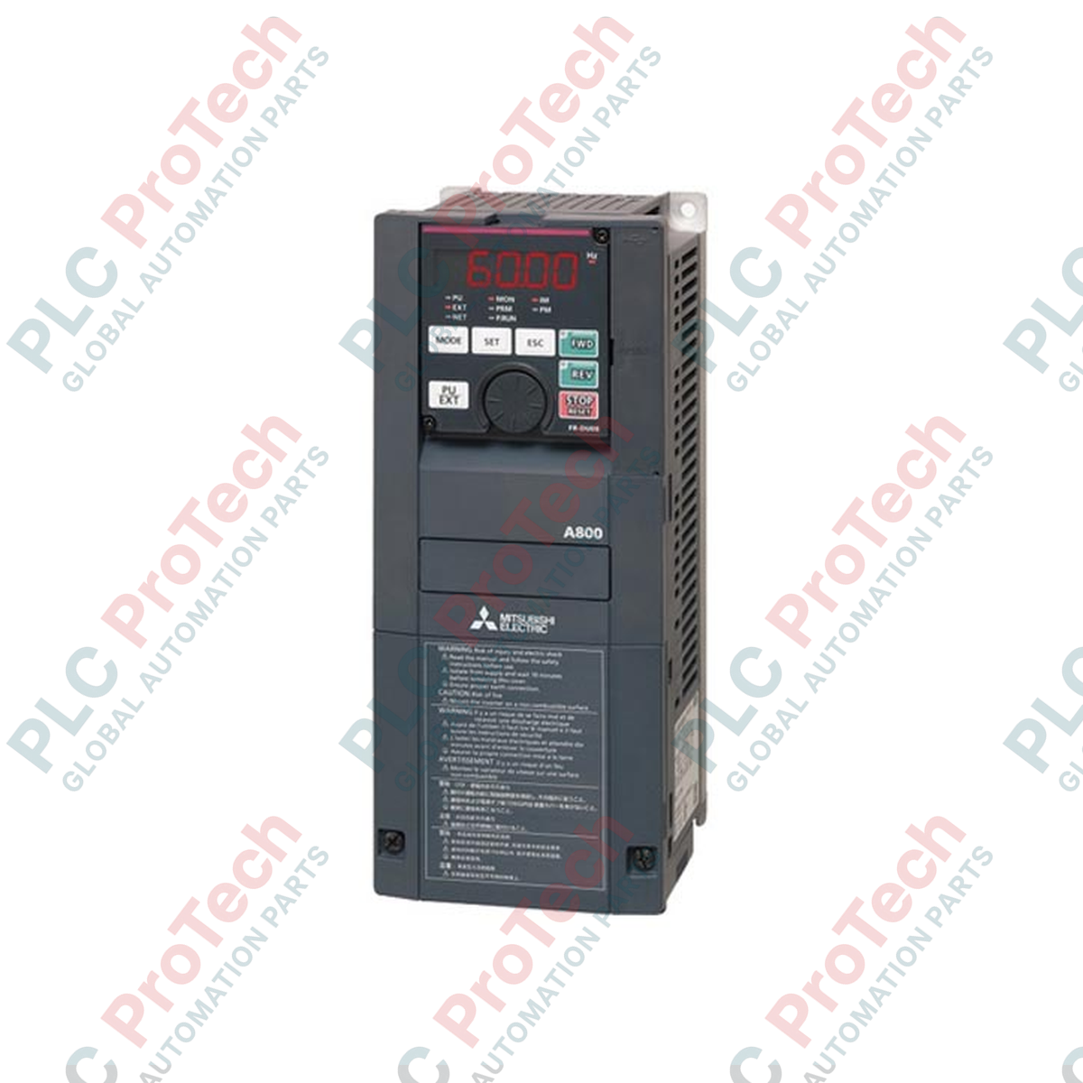
Designed for high-performance industrial motor control, the FR-A840-1.5K-1 by Mitsubishi Electric operates as a premium variable frequency drive within the FR-A800 series. This high-capacity inverter delivers exceptional speed and torque control for 1.5 kW three-phase motors, relying on advanced real-time sensorless vector control algorithms. Built to withstand demanding manufacturing environments, the unit integrates standard serial communication architectures, high-efficiency cooling, and robust overcurrent protection to ensure continuous field operation and minimize plant downtime.
| Parameter | Value |
|---|---|
| Manufacturer | Mitsubishi Electric |
| Model Reference | FR-A840-1.5K-1 |
| Series Name | FR-A800 |
| Input Voltage Class | Three-phase 400 V (380 to 500 VAC, 50/60 Hz) |
| Applicable Motor Capacity | 1.5 kW |
| Output Rated Current | 4.0 A |
| Output Rated Capacity | 3.0 kVA |
| Communication Interfaces | RS-232, RS-422, RS-485 (Mitsubishi / Modbus RTU) |
| Standards & Approvals | CE, UL, cUL, RoHS |
| Enclosure Rating | IP20 |
| Physical Dimensions (H x W x D) | 260 mm x 150 mm x 140 mm |
| Shipping Weight (Calculated) | 4.5 kg |
| Terminal Designation | Circuit / Function Assignment |
|---|---|
| R/L1, S/L2, T/L3 | Main Three-Phase AC Power Input Connection |
| U, V, W | Three-Phase Variable Frequency Output to Motor |
| P/+, PR | Braking Resistor Connection Terminals |
| STF / STR | Forward Run Start / Reverse Run Start Digital Inputs |
| SD | Common Terminal for Digital Inputs and 24 VDC Power source |
| 2, 4, 5 | Analog Frequency Setting Inputs (Voltage / Current) & Common Ground |
The FR-A840-1.5K-1 serves as the direct technological replacement for legacy FR-A740-1.5K series drive models. While the footprint and control terminals line up similarly, please note that parameter structures have expanded. When utilizing FR Configurator2 software to import existing parameter files from A700 series models, a careful verification of acceleration-deceleration curve parameters and motor tuning maps must be performed to ensure smooth commissioning.
During integration inside IP54 enclosed control panels, local heat dissipation must be handled correctly. The drive requires a minimum space clear-zone of 50 mm above and below the chassis for unimpeded natural airflow. In applications operating continuously at low speeds under high-torque demand, the integrated motor fan will lose efficiency. Always implement an external forced cooling fan on the motor or utilize inverter-duty rated motors to prevent winding thermal trips (E.THT faults).
Ensure that Parameter 79 (Operation Mode Selection) is explicitly set to match your system master. For example, setting Pr.79 to "2" locks control logic exclusively to the external terminals, bypassing the PU keypad. For RS-485 serial communication daisy chains, apply a terminating resistor on the final physical node and run standard double-shielded twisted pair (STP) control cables. The shield must be terminated strictly at a single point (PE ground at the cabinet entry) to prevent destructive ground loops.
CRITICAL WARNING
Isolate all main power lines prior to physical cabinet mounting or control terminal wiring. Once input power is switched off, wait a minimum of 10 minutes for the internal DC bus capacitors to fully discharge. Always measure the DC bus voltage across terminals P/+ and N/- using a calibrated digital multimeter to verify the potential is below 50 VDC before initiating touch-sensitive electrical tasks.
Securely mount the variable speed drive on a rigid, vibration-resistant vertical panel backplate using appropriate M5 bolts.
Connect the physical PE protective ground terminal directly to the central cabinet earth bar before wiring power supply lines.
Terminate the three-phase power lines at R/L1, S/L2, and T/L3, ensuring correct phase configuration, and route the motor outputs from U, V, and W.
Secure control signal wiring away from the high-voltage power lines inside separate wire ducting lanes to prevent inductive cross-talk.
Global Express Shipping
Returns & Warranty
Orders are processed and delivered Monday-Friday (excluding public holidays).
For full eligibility, restocking fees, and international return details, please view our official Refund & Return Policy .
| Country of origin |
United States
|

Implement a 3-SPST switch XOR light circuit in LogixPro or RSLogix 500 using an internal relay bit. Includes truth tables, boolean equations, and verified.

Integrate Allen-Bradley CompactLogix, Caterpillar ATS, and generators into DeltaV DCS over Modbus RTU. Covers ProSoft MVI69-MCM, Miille DIN266 gateways.

ONS instruction fires but the OTE coil never latches in Studio 5000 because the one-shot is only true for one scan. Use OTL/OTU or seal-in logic instead.

Configure Allen-Bradley Kinetix 5500 servo drives on EtherNet/IP. Covers CIP Sync, IEEE 1588 V2 timing, Stratix selection, DLR topology, and HMI.

A moving-average filter is the sliding-window smoother most instrument engineers drop into DCS and PLC analog paths. Here is how the window works, how N and sample time set lag, and when a...

On Frame 5–9 gas turbines, GE Mark VI and Mark VIe run control as function-block application software. This article maps process, protection, and sequencing functions—and what Toolbox ST access...