Description
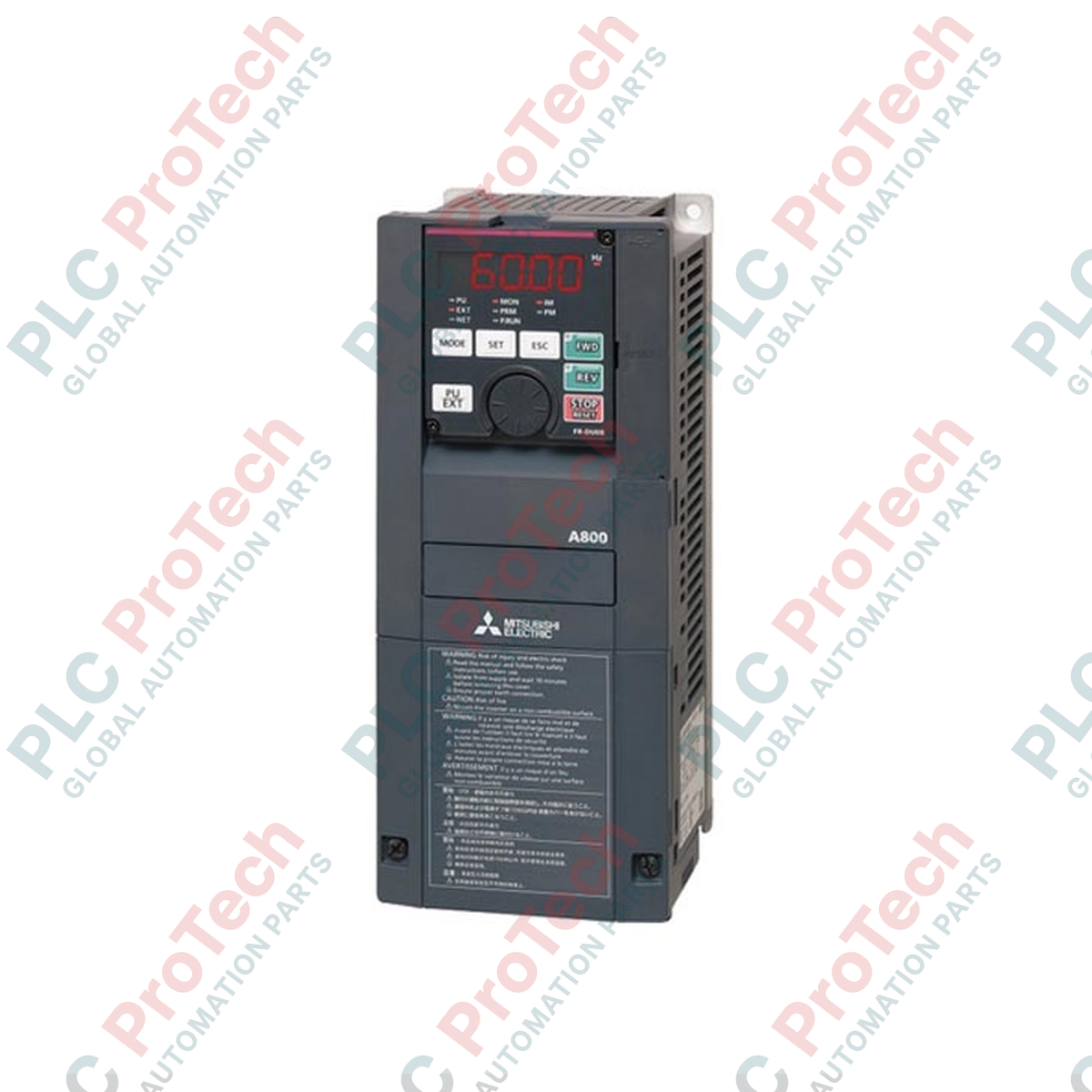
Designed for heavy-duty industrial motor control, the Mitsubishi Electric FR-A840-15K-1 operates as a high-performance variable frequency drive engineered for high-torque and precision speed regulation. Part of the flagship FR-A800 series, this three-phase inverter incorporates advanced vector control algorithms to drive induction and permanent magnet motors with exceptional stability. It features an integrated 15 kW rated power capacity and built-in RS-485/422/232 interfaces, facilitating seamless integration into distributed control architectures. Designed for demanding applications such as extruders, centrifuges, and gantry cranes, this robust drive delivers high starting torque and precise velocity loop tuning to maintain operational uptime in harsh environments.
Features
-
Real Sensorless Vector Control: Achieves zero-speed high-torque control without requiring an encoder feedback interface.
-
Dual Overload Rating: Configurable for Normal Duty (ND) and Light Duty (LD) operational profiles to optimize motor performance.
-
Built-in PLC Functionality: Executes decentralized control logic and custom I/O configurations directly inside the drive processor.
-
Enhanced Safety: Built-in dual-channel emergency stop circuit conforming to ISO 13849-1 PLd / SIL2 standards.
-
Energy Optimization: Dynamic energy-saving algorithms adjust magnetic flux in response to shifting load demands.
Applications
- High-inertia mechanical systems including industrial centrifuges and mixers.
- Material handling systems, overhead hoists, and positioning gantries.
- Heavy manufacturing machinery such as extruders, winders, and heavy-duty conveyor systems.
- Variable torque applications including large-scale industrial fan arrays and high-pressure pumping stations.
Technical Specifications
| Parameter |
Specification Value |
| Manufacturer |
Mitsubishi Electric |
| Model Reference |
FR-A840-15K-1 |
| Series |
FR-A800 |
| Applicable Motor Capacity |
15 kW (Normal Duty) |
| Input Voltage Class |
Three-Phase 380 to 500 V AC, 50/60 Hz |
| Output Rated Voltage |
Three-Phase 380 to 500 V AC (proportional to input voltage) |
| Output Capacity |
18 kVA |
| Embedded Communication |
RS-232, RS-422, RS-485 (Modbus-RTU) |
| Protective Structure |
IP20 (Closed Type) |
| Representative Standard |
CE, UL, cUL |
| Dimensions (W x H x D) |
220 mm x 300 mm x 190 mm |
| Shipping Weight (Calculated) |
9.5 kg |
Connections and Interfaces
| Terminal Symbol |
Description / Functional Assignment |
| R/L1, S/L2, T/L3 |
Three-phase AC power supply input terminals. |
| U, V, W |
Three-phase AC output connections to the induction/PM motor. |
| P/+, PR |
Connection terminals for optional external dynamic braking resistor. |
| STF / STR |
Forward Start / Reverse Start command inputs. |
| SD |
Common terminal for control input signals (isolated from analog common 5). |
| 10, 2, 5 |
Analog speed setting input (+10V reference, 0-5V/0-10V input, analog common). |
Empirical Engineering Insights
Alternative Models & Compatibility
This drive directly replaces legacy FR-A740-15K systems. While mounting footprints are physically identical, configuration parameters must be migrated. When commissioning via FR Configurator2 software, verify that parameter Pr. 189 (LDT detection level) and Pr. 570 (Multiple rating setting) are correctly configured to correspond with the load profile of the legacy unit.
Application Pitfalls & Engineering Notes
Operating this drive in closed, unventilated panels at ambient temperatures exceeding 40 degC requires a 10% derating of output current. Running the carrier frequency (Pr. 72) above 2 kHz on long motor cable runs (greater than 50 meters) can induce capacitive leakage currents, triggering E.THT (Inverter overload) or E.OC1 (Overcurrent during acceleration) faults.
Commissioning & Wiring Tips
To prevent electromagnetic interference in the analog speed reference loop, separate the 0-10V signal lines (Terminals 2 and 5) from high-voltage motor output lines by at least 30 cm. Ground the motor frame directly to the inverter's earth terminal and ensure the shield of the control cable is connected to earth at the drive side only.
Installation Guidelines
CRITICAL WARNING
Isolate all primary and control power sources before making physical connections to the drive. Wait at least 10 minutes after disconnecting power to allow internal bus capacitors to discharge. Always verify that the DC link voltage across terminals P/+ and N/- is below 30 VDC using a calibrated voltmeter before proceeding.
1
Mount the inverter vertically inside a dust-free and moisture-protected electrical enclosure, ensuring a minimum clearance of 50 mm above and below the cooling fans.
2
Connect the incoming three-phase supply power to mains input terminals R/L1, S/L2, and T/L3. Do not connect input power to output terminals U, V, and W.
3
Route motor output cables through a dedicated grounded conduit to terminals U, V, and W, maintaining physical separation from control and instrumentation cabling.
4
Connect control signals and safety circuits to the spring-clamp terminal block, ensuring correct configuration of sink/source logic switch.