


Implementing 3-Switch XOR Ladder Logic with Internal Bit
Implement a 3-SPST switch XOR light circuit in LogixPro or RSLogix 500 using an internal relay bit. Includes truth tables, boolean equations, and verified.

Engineered for high-demand heavy industrial applications, the Mitsubishi Electric FR-A840-75K-1 variable frequency drive delivers precise speed and torque control for motors up to 75 kW. Incorporating advanced vector control algorithm technologies, this three-phase 400V class inverter maximizes operational uptime and system efficiency in demanding processing environments. The unit features a dedicated FM terminal configured for high-speed pulse train output, enabling real-time feedback and seamless integration into higher-level DCS and PLC architectures.
| Specification Parameter | Value / Rating |
|---|---|
| Manufacturer | Mitsubishi Electric |
| Model Number | FR-A840-75K-1 |
| Applicable Motor Capacity | 75 kW (Heavy Duty) / 90 kW (Normal Duty) |
| Input Voltage Class | Three-Phase 380 to 500 V AC (50/60 Hz) |
| Rated Output Current | 144 A (Heavy Duty) / 180 A (Normal Duty) |
| Output Capacity | 110 kVA |
| Control Method | V/F Control, Advanced Magnetic Flux Vector Control, Real Sensorless Vector Control |
| Monitor Output Terminal | Terminal FM (Pulse Train Type) |
| Communication Protocols | RS-422, RS-485 (Built-in Modbus RTU) |
| Protective Rating | IP00 (Open Type) |
| Operating Temperature | -10 degC to +50 degC (Non-freezing) |
| Compliance & Certifications | CE, UL, cUL, RoHS compliant |
| Country of Origin | Japan |
| Shipping Weight (Calculated) | 53.0 kg (116.8 lbs) |
| Physical Dimensions (W x H x D) | 465 mm x 595 mm x 300 mm |
The FR-A840-75K-1 serves as the direct replacement for the legacy FR-A740-75K model series. While the footprint and control terminal layouts are largely identical, parameter migration must be handled carefully. When upgrading, parameters should be exported via FR Configurator2 software to ensure custom logic programs and PID loop configurations translate correctly. Note that the "-1" suffix designates the unit equipped with the FM terminal interface (pulse output) as opposed to the "-2" suffix which features an AM terminal (analog voltage output).
Operating a 75 kW high-capacity drive generates substantial thermal loads, approximately 1850 Watts of heat dissipation at full capacity. Enclosing this unit within sealed IP54 panels requires forced mechanical cooling to prevent the internal heatsink from exceeding 50 degC, which triggers an overtemperature warning (E.THT). Additionally, installing an external DC link reactor (FR-HEL) is highly recommended to protect the rectifier bridge from input line surges and reduce high-frequency harmonic feedback into the distribution transformer.
When routing cables for the FM pulse output terminal, use braided, shielded twisted-pair (STP) wiring with a minimum wire cross-section of 0.75 mm2. Keep control cables physically isolated from the output motor phases (U, V, W) by a distance of at least 30 cm to prevent EMI noise injection, which can distort pulse output readings. If the drive displays an E.UVT (Undervoltage) fault during ramp-up, verify that the input voltage supply does not sag below 323 V AC under transient loading conditions.
CRITICAL WARNING: HIGH VOLTAGE RISK
Isolate all primary feed circuits before executing installation. Wait a minimum of 10 minutes post-power-down to allow internal DC bus capacitors to discharge below safety thresholds. Confirm that the DC bus voltage across terminals P/+ and N/- is measured at 0 V with a rated digital multimeter before initiating terminal modifications.
Mount the drive vertically on a flat, non-flammable vertical backplate to optimize convection cooling currents across the heatsink assembly.
Connect the mains power cabling to terminals R/L1, S/L2, and T/L3. Connect the output motor cabling to terminals U, V, and W. Ensure all ground lugs are connected to a low-impedance facility earth bus.
Perform a dry run setup with the motor disconnected. Set Parameter 9 (Motor Rated Current) and Parameter 71 (Applied Motor Selection) via the onboard PU display before running an autotuning sequence.
Global Express Shipping
Returns & Warranty


Manufacturer: Mitsubishi Electric
Product No.: FR-A840-75K-1
Country of origin:United States
Product Type: Variable Frequency Drives
Payment: T/T, Western Union
Weight: 53000g
Dimensions: 465 mm x 595 mm x 300 mm
Shipping port: Xiamen
Warranty: 12 months
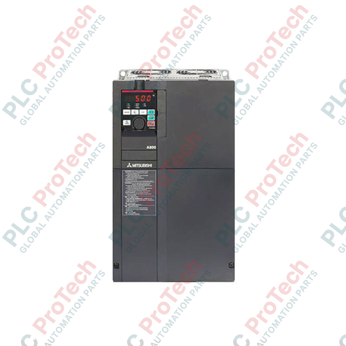
Engineered for high-demand heavy industrial applications, the Mitsubishi Electric FR-A840-75K-1 variable frequency drive delivers precise speed and torque control for motors up to 75 kW. Incorporating advanced vector control algorithm technologies, this three-phase 400V class inverter maximizes operational uptime and system efficiency in demanding processing environments. The unit features a dedicated FM terminal configured for high-speed pulse train output, enabling real-time feedback and seamless integration into higher-level DCS and PLC architectures.
| Specification Parameter | Value / Rating |
|---|---|
| Manufacturer | Mitsubishi Electric |
| Model Number | FR-A840-75K-1 |
| Applicable Motor Capacity | 75 kW (Heavy Duty) / 90 kW (Normal Duty) |
| Input Voltage Class | Three-Phase 380 to 500 V AC (50/60 Hz) |
| Rated Output Current | 144 A (Heavy Duty) / 180 A (Normal Duty) |
| Output Capacity | 110 kVA |
| Control Method | V/F Control, Advanced Magnetic Flux Vector Control, Real Sensorless Vector Control |
| Monitor Output Terminal | Terminal FM (Pulse Train Type) |
| Communication Protocols | RS-422, RS-485 (Built-in Modbus RTU) |
| Protective Rating | IP00 (Open Type) |
| Operating Temperature | -10 degC to +50 degC (Non-freezing) |
| Compliance & Certifications | CE, UL, cUL, RoHS compliant |
| Country of Origin | Japan |
| Shipping Weight (Calculated) | 53.0 kg (116.8 lbs) |
| Physical Dimensions (W x H x D) | 465 mm x 595 mm x 300 mm |
The FR-A840-75K-1 serves as the direct replacement for the legacy FR-A740-75K model series. While the footprint and control terminal layouts are largely identical, parameter migration must be handled carefully. When upgrading, parameters should be exported via FR Configurator2 software to ensure custom logic programs and PID loop configurations translate correctly. Note that the "-1" suffix designates the unit equipped with the FM terminal interface (pulse output) as opposed to the "-2" suffix which features an AM terminal (analog voltage output).
Operating a 75 kW high-capacity drive generates substantial thermal loads, approximately 1850 Watts of heat dissipation at full capacity. Enclosing this unit within sealed IP54 panels requires forced mechanical cooling to prevent the internal heatsink from exceeding 50 degC, which triggers an overtemperature warning (E.THT). Additionally, installing an external DC link reactor (FR-HEL) is highly recommended to protect the rectifier bridge from input line surges and reduce high-frequency harmonic feedback into the distribution transformer.
When routing cables for the FM pulse output terminal, use braided, shielded twisted-pair (STP) wiring with a minimum wire cross-section of 0.75 mm2. Keep control cables physically isolated from the output motor phases (U, V, W) by a distance of at least 30 cm to prevent EMI noise injection, which can distort pulse output readings. If the drive displays an E.UVT (Undervoltage) fault during ramp-up, verify that the input voltage supply does not sag below 323 V AC under transient loading conditions.
CRITICAL WARNING: HIGH VOLTAGE RISK
Isolate all primary feed circuits before executing installation. Wait a minimum of 10 minutes post-power-down to allow internal DC bus capacitors to discharge below safety thresholds. Confirm that the DC bus voltage across terminals P/+ and N/- is measured at 0 V with a rated digital multimeter before initiating terminal modifications.
Mount the drive vertically on a flat, non-flammable vertical backplate to optimize convection cooling currents across the heatsink assembly.
Connect the mains power cabling to terminals R/L1, S/L2, and T/L3. Connect the output motor cabling to terminals U, V, and W. Ensure all ground lugs are connected to a low-impedance facility earth bus.
Perform a dry run setup with the motor disconnected. Set Parameter 9 (Motor Rated Current) and Parameter 71 (Applied Motor Selection) via the onboard PU display before running an autotuning sequence.
Global Express Shipping
Returns & Warranty
Orders are processed and delivered Monday-Friday (excluding public holidays).
For full eligibility, restocking fees, and international return details, please view our official Refund & Return Policy .
| Country of origin |
United States
|

Implement a 3-SPST switch XOR light circuit in LogixPro or RSLogix 500 using an internal relay bit. Includes truth tables, boolean equations, and verified.

Integrate Allen-Bradley CompactLogix, Caterpillar ATS, and generators into DeltaV DCS over Modbus RTU. Covers ProSoft MVI69-MCM, Miille DIN266 gateways.

ONS instruction fires but the OTE coil never latches in Studio 5000 because the one-shot is only true for one scan. Use OTL/OTU or seal-in logic instead.

Configure Allen-Bradley Kinetix 5500 servo drives on EtherNet/IP. Covers CIP Sync, IEEE 1588 V2 timing, Stratix selection, DLR topology, and HMI.

A moving-average filter is the sliding-window smoother most instrument engineers drop into DCS and PLC analog paths. Here is how the window works, how N and sample time set lag, and when a...

On Frame 5–9 gas turbines, GE Mark VI and Mark VIe run control as function-block application software. This article maps process, protection, and sequencing functions—and what Toolbox ST access...