Description
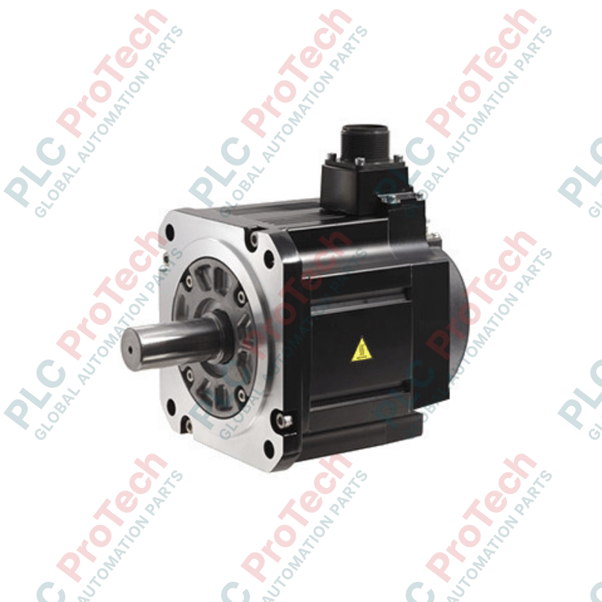
Engineered to handle high-inertia industrial loads with high precision, the Mitsubishi Electric HG-SN102BJ-S100 AC servo motor delivers stable torque output and reliable performance within modern manufacturing systems. Operating at a rated output of 1.0 kW and a rated speed of 2000 r/min, this model is built with an integrated electromagnetic safety brake and a factory-installed oil seal to prevent fluid ingress, making it well-suited for demanding environmental conditions.
Features
- High-inertia design optimized for applications with fluctuating loads.
- Built-in 24VDC electromagnetic brake for reliable safety holding and emergency stops.
- Factory-installed shaft oil seal protecting internal components from industrial lubricants and cutting fluids.
- Robust IP67-rated enclosure (excluding shaft-through portion) allowing installation in dusty or wet environments.
- Class 155 (F) thermal insulation ensuring stable operational integrity under heavy duty cycles.
Applications
- Automated material handling and packaging systems.
- Heavy-duty rotary index tables and positioning axes.
- Textile processing machinery and winding equipment.
- Machine tool auxiliary axes requiring brake-hold capabilities during power-loss events.
Technical Specifications
| Parameter |
Value |
| Manufacturer |
Mitsubishi Electric |
| Model Number |
HG-SN102BJ-S100 |
| Series |
HG-SN Series |
| Rated Output |
1.0 kW |
| Rated Torque |
4.77 N-m |
| Rated Speed |
2000 r/min |
| Maximum Speed |
3000 r/min |
| Rated Current |
5.6 A |
| Maximum Current |
17.0 A |
| Electromagnetic Brake |
Yes (Integrated, 24VDC holding type) |
| Oil Seal |
Yes (Installed) |
| Insulation Class |
155 (F) |
| IP Rating |
IP67 (excluding shaft-through portion) |
| Ambient Operating Temperature |
0 to 40 degC (non-freezing) |
| Net Weight |
8.2 kg |
| Shipping Weight (Calculated) |
10.0 kg |
Empirical Engineering Insights
Alternative Models & Compatibility
The "BJ" suffix specifies both an integrated brake ("B") and an oil seal ("J"). While standard models like the HG-SN102 are physically compatible in terms of frame size and shaft dimension, switching to a non-B or non-J variant will require modification of the PLC control safety circuit and may compromise seal protection in wet environments. Confirm that your drive parameter set matches the S100 special specifications configuration if replacing a customized factory-run motor.
Application Pitfalls & Engineering Notes
Maintain a load-to-motor inertia ratio of 15 times or less. Exceeding this limit leads to positioning overshoot, loop instability, and recurring overcurrent faults (such as AL.50 or AL.30 on associated MELSERVO drives). If your system demands high deceleration frequencies under high-inertia loads, integrate an external dynamic braking or regenerative resistor array to protect the drive's internal capacitors.
Commissioning & Wiring Tips
Always suppress voltage spikes from the 24VDC electromagnetic brake by wiring a surge-absorbing varistor in parallel with the brake coil. Do not share the 24VDC brake power supply with the PLC controller's I/O power circuit, as switching inductive brake loads introduces electrical noise that can drop local control rails or cause intermittent encoder communication faults.
Installation Guidelines
CRITICAL WARNING: Prior to beginning installation, lock out and tag out all primary and auxiliary power sources feeding the servo amplifier and the brake control system. Wait a minimum of 15 minutes to allow residual charge in the amplifier's DC bus capacitors to discharge. Verify zero-voltage status with a calibrated digital multimeter before contacting motor terminals or connections.
1
Mount the motor on a flat, rigid metal surface designed to act as a heat sink. Ensure the mating surface is clean of debris, paint, and rust protectants.
2
Verify shaft alignment to avoid excess radial and axial loads. Use a flexible coupling rated for high-torque servo operation to prevent mechanical fatigue on the motor bearings.
3
Route cables with a continuous drip loop if liquid runoff is expected near the connectors. Ground the motor frame securely to the main electrical panel ground plate using a heavy-gauge, low-impedance grounding strap.