


Implementing 3-Switch XOR Ladder Logic with Internal Bit
Implement a 3-SPST switch XOR light circuit in LogixPro or RSLogix 500 using an internal relay bit. Includes truth tables, boolean equations, and verified.

Designed for high-speed multi-axis synchronization within the MELSEC L series platform, the Mitsubishi Electric LD77MH16 provides advanced motion, positioning, and synchronous control via a high-performance fiber optic network. This high-density positioning module supports up to 16 axes of motion over SSCNET III/H, delivering robust noise immunity and rapid command transmission for demanding industrial machinery. Featuring built-in digital inputs for high-speed registration, the device functions as a central command interface to bridge PLC logic with servo amplifier execution without sacrificing backplane performance.
| Parameter | Specification |
|---|---|
| Manufacturer | Mitsubishi Electric |
| Model Code | LD77MH16 |
| Module Type | Simple Motion Module |
| Number of Control Axes | 16 Axes |
| Servo Amplifier Interface | SSCNET III/H (50 Mbps Optical Fiber) |
| Input Points | 4 Points |
| Input Circuit Isolation | Photocoupler |
| Rated Input Voltage | 24 VDC |
| Operating Voltage Range | 21.6 to 26.4 VDC (Ripple ratio 5% or less) |
| Rated Input Current | Approx. 5 mA |
| ON Voltage / Current | 17.5 VDC or more / 3.5 mA or more |
| OFF Voltage / Current | 5 VDC or less / 0.9 mA or less |
| Input Resistance | Approx. 5.6 kOhm |
| Response Time | 1 ms or less |
| Recommended Wire Size | AWG24 (0.2 mm²) |
| Internal Current Consumption (5 VDC) | 0.70 A |
| Country of Origin | Japan |
| Module Net Weight | 0.22 kg |
| Shipping Weight (Calculated) | 2.00 kg |
| Connector / Interface | Function / Circuit Assignment |
|---|---|
| CN1A Port | SSCNET III/H Optical Link Inbound Connection |
| CN1B Port | SSCNET III/H Optical Link Outbound/Downstream Connection |
| External Input Connector | 24 VDC Digital Inputs (Points 1-4) for limit, stop, or touch probe signals |
The LD77MH16 is the 16-axis variant of the MELSEC L positioning line. For systems requiring fewer axes, the hardware-identical LD77MH4 (4-axis) serves as a drop-in software-subset alternative. When migrating software configurations from Q-series QD77MS modules, confirm that buffer memory allocations match, as the L-series architecture maps configuration blocks slightly differently within the global address space.
The fiber-optic system relies entirely on optical signal integrity. Ensure that the MR-J3BUS optical cables do not exceed their rated minimum bend radius. Excessively sharp bends cause high signal attenuation, leading to intermittent communication dropouts, "SSCNET Frame Error" faults, or unexpected servo disconnects under high-vibration operating conditions.
When configuring absolute encoder systems, ensure that absolute coordinates are initialized correctly in the Simple Motion Setting Tool. Ensure the 24 VDC external registration inputs are routed using shielded, twisted-pair cabling. Keep these lines separated from high-current AC servo power runs to eliminate capacitive coupling, which can cause false registration triggers.
Align and mount the module securely to the DIN rail, ensuring the unit is interlocked properly with adjacent L-series modules using the built-in side-locking levers.
Remove protective caps from the CN1A/CN1B optical transceiver ports and connect the SSCNET III/H fiber optic cables. Keep dust caps securely stored for future maintenance.
Terminate the 24 VDC field input wires to the external connector block using AWG24 shielded lines, and verify proper ground loop mitigation before applying power.
Global Express Shipping
Returns & Warranty


Manufacturer: Mitsubishi Electric
Product No.: LD77MH16
Country of origin:United States
Product Type: Simple Motion Modules
Payment: T/T, Western Union
Weight: 2000g
Shipping port: Xiamen
Warranty: 12 months
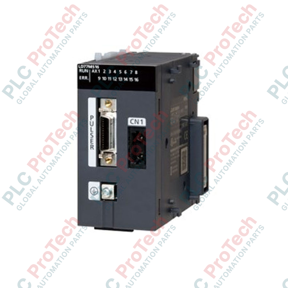
Designed for high-speed multi-axis synchronization within the MELSEC L series platform, the Mitsubishi Electric LD77MH16 provides advanced motion, positioning, and synchronous control via a high-performance fiber optic network. This high-density positioning module supports up to 16 axes of motion over SSCNET III/H, delivering robust noise immunity and rapid command transmission for demanding industrial machinery. Featuring built-in digital inputs for high-speed registration, the device functions as a central command interface to bridge PLC logic with servo amplifier execution without sacrificing backplane performance.
| Parameter | Specification |
|---|---|
| Manufacturer | Mitsubishi Electric |
| Model Code | LD77MH16 |
| Module Type | Simple Motion Module |
| Number of Control Axes | 16 Axes |
| Servo Amplifier Interface | SSCNET III/H (50 Mbps Optical Fiber) |
| Input Points | 4 Points |
| Input Circuit Isolation | Photocoupler |
| Rated Input Voltage | 24 VDC |
| Operating Voltage Range | 21.6 to 26.4 VDC (Ripple ratio 5% or less) |
| Rated Input Current | Approx. 5 mA |
| ON Voltage / Current | 17.5 VDC or more / 3.5 mA or more |
| OFF Voltage / Current | 5 VDC or less / 0.9 mA or less |
| Input Resistance | Approx. 5.6 kOhm |
| Response Time | 1 ms or less |
| Recommended Wire Size | AWG24 (0.2 mm²) |
| Internal Current Consumption (5 VDC) | 0.70 A |
| Country of Origin | Japan |
| Module Net Weight | 0.22 kg |
| Shipping Weight (Calculated) | 2.00 kg |
| Connector / Interface | Function / Circuit Assignment |
|---|---|
| CN1A Port | SSCNET III/H Optical Link Inbound Connection |
| CN1B Port | SSCNET III/H Optical Link Outbound/Downstream Connection |
| External Input Connector | 24 VDC Digital Inputs (Points 1-4) for limit, stop, or touch probe signals |
The LD77MH16 is the 16-axis variant of the MELSEC L positioning line. For systems requiring fewer axes, the hardware-identical LD77MH4 (4-axis) serves as a drop-in software-subset alternative. When migrating software configurations from Q-series QD77MS modules, confirm that buffer memory allocations match, as the L-series architecture maps configuration blocks slightly differently within the global address space.
The fiber-optic system relies entirely on optical signal integrity. Ensure that the MR-J3BUS optical cables do not exceed their rated minimum bend radius. Excessively sharp bends cause high signal attenuation, leading to intermittent communication dropouts, "SSCNET Frame Error" faults, or unexpected servo disconnects under high-vibration operating conditions.
When configuring absolute encoder systems, ensure that absolute coordinates are initialized correctly in the Simple Motion Setting Tool. Ensure the 24 VDC external registration inputs are routed using shielded, twisted-pair cabling. Keep these lines separated from high-current AC servo power runs to eliminate capacitive coupling, which can cause false registration triggers.
Align and mount the module securely to the DIN rail, ensuring the unit is interlocked properly with adjacent L-series modules using the built-in side-locking levers.
Remove protective caps from the CN1A/CN1B optical transceiver ports and connect the SSCNET III/H fiber optic cables. Keep dust caps securely stored for future maintenance.
Terminate the 24 VDC field input wires to the external connector block using AWG24 shielded lines, and verify proper ground loop mitigation before applying power.
Global Express Shipping
Returns & Warranty
Orders are processed and delivered Monday-Friday (excluding public holidays).
For full eligibility, restocking fees, and international return details, please view our official Refund & Return Policy .
| Country of origin |
United States
|

Implement a 3-SPST switch XOR light circuit in LogixPro or RSLogix 500 using an internal relay bit. Includes truth tables, boolean equations, and verified.

Integrate Allen-Bradley CompactLogix, Caterpillar ATS, and generators into DeltaV DCS over Modbus RTU. Covers ProSoft MVI69-MCM, Miille DIN266 gateways.

ONS instruction fires but the OTE coil never latches in Studio 5000 because the one-shot is only true for one scan. Use OTL/OTU or seal-in logic instead.

Configure Allen-Bradley Kinetix 5500 servo drives on EtherNet/IP. Covers CIP Sync, IEEE 1588 V2 timing, Stratix selection, DLR topology, and HMI.

A moving-average filter is the sliding-window smoother most instrument engineers drop into DCS and PLC analog paths. Here is how the window works, how N and sample time set lag, and when a...

On Frame 5–9 gas turbines, GE Mark VI and Mark VIe run control as function-block application software. This article maps process, protection, and sequencing functions—and what Toolbox ST access...