Mitsubishi Electric

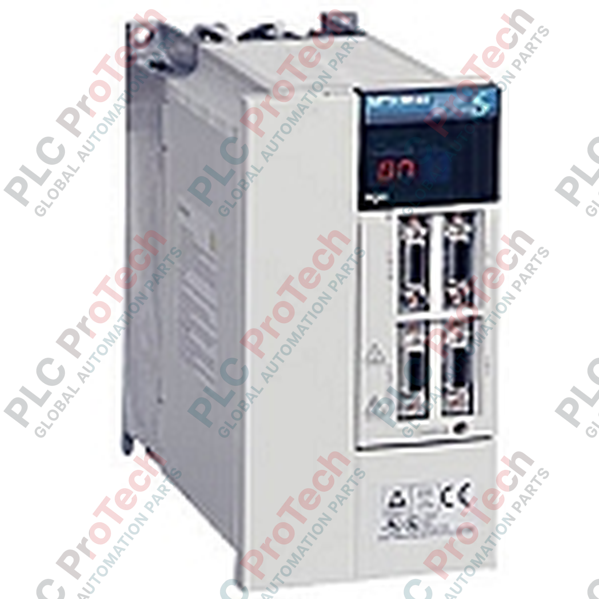
Mitsubishi Electric MR-J2S-100A MELSERVO J2-Super Series AC Servo Amplifier

SKU MR-J2S-100A

In stock
  • 12-month warranty
  • Free returns within 30 days
  • Manufacturer: Mitsubishi Electric

  • Product No.: MR-J2S-100A

  • Country of origin:United States

  • Product Type: AC Servo Drives

  • Payment: T/T, Western Union

  • Weight: 500g

  • Dimensions: 280 x 210 x 130 mm

  • Shipping port: Xiamen

  • Warranty: 12 months

Engineered to deliver high-precision motion control within automated systems, the Mitsubishi Electric MR-J2S-100A servo amplifier provides robust closed-loop regulation for industrial positioning applications. This 1.0 kW drive module integrates seamlessly into standard control architectures, accepting both analog commands and high-speed pulse train inputs to drive compatible MELSERVO rotary motors with exceptional dynamic response.

Key Features

  • High-Resolution Feedback: Fully compatible with 17-bit (131072 pulses/revolution) absolute and incremental encoders for superior positioning accuracy.
  • Versatile Control Modes: Supports Position, Speed, and Torque control modes, with the ability to switch modes via external I/O commands.
  • Real-Time Auto-Tuning: Continuously analyzes mechanical load inertia and automatically adjusts gain parameters during operation.
  • Integrated Protection Circuits: Built-in safeguards against overcurrent, regenerative overvoltage, overload, encoder communication faults, and thermal runaway.
  • Compact Footprint: Optimized heatsink design allows for dense control cabinet layouts with minimal spacing requirements.

Applications

  • Multi-axis CNC machining centers and precision milling machinery.
  • High-speed packaging, labeling, and material handling systems.
  • Automated pick-and-place gantry robots and Cartesian coordinate systems.
  • Semiconductor manufacturing and wafer processing equipment.
  • Textile machinery and printing press tension control systems.

Technical Specifications

Parameter Specification Value
Manufacturer Mitsubishi Electric
Model Number MR-J2S-100A
Series MELSERVO J2-Super
Rated Output Power 1.0 kW (1000 Watts)
Main Circuit Power Supply 3-phase 200-230 VAC, 50/60 Hz
Permissible Voltage Fluctuation 3-phase 170-253 VAC
Control Circuit Power Supply 1-phase 200-230 VAC, 50/60 Hz
Control System Sinusoidal PWM control / current control system
Speed Frequency Response 550 Hz or more
Dynamic Brake Built-in
Cooling Method Forced cooling (integrated fan)
Enclosure Rating IP00 (Open type)
Country of Origin Japan
Shipping Weight (Calculated) 3.0 kg
Package Dimensions (Calculated) 280 x 210 x 130 mm

Connections and Interfaces

Connector / Terminal Function / Circuit Assignment
L1, L2, L3 Main AC power input terminals (3-phase 200-230 VAC)
L11, L21 Control circuit AC power input terminals (1-phase 200-230 VAC)
U, V, W Servo motor power output connections (Phase U, V, W)
P, C, D Regenerative option terminals (short-circuit bar between P and D for internal resistor)
CN1A / CN1B Control I/O, pulse train input, and analog command interfaces
CN2 Encoder feedback connector (10-pin high-density interface)
CN3 RS-232C / RS-422 serial communication port for PC connection

Empirical Engineering Insights

Alternative Models & Compatibility

The MR-J2S-100A is the direct, enhanced successor to the legacy MR-J2-100A amplifier. When migrating from the older J2 series, parameters must be converted using the MR Configurator software (Setup121E or newer). Note that physical mounting dimensions are identical, but the J2S features improved encoder processing algorithms, meaning older J2 motors may require parameter adjustments to prevent initialization errors.

Application Pitfalls & Engineering Notes

In high-inertia or rapid deceleration applications, the internal regenerative resistor can overheat, triggering an AL.30 (Regenerative Error). If this occurs, install an external regenerative resistor (such as the MR-RB32) across terminals P and C, and ensure the factory-installed short-circuit bar between P and D is completely removed. Failure to remove this bar when using an external resistor will damage the internal drive circuitry.

Commissioning & Wiring Tips

During initial bench testing or commissioning without a host controller, the drive will display a persistent AL.E6 (Emergency Stop) fault. To bypass this for testing, wire a physical jumper between terminal EMG (CN1A, pin 15) and SG (CN1A, pin 10). Always ensure that the encoder cable connected to CN2 uses double-shielded twisted-pair cabling with the shield terminated directly to the connector shell to mitigate high-frequency EMI.

Installation Guidelines

CRITICAL WARNING: Ensure all AC input power (L1, L2, L3 and L11, L21) is completely disconnected and verify that the charge LED on the front panel is fully extinguished before touching any terminals. Residual DC bus voltage can exceed 300 VDC and remains present for several minutes after power-off.
1

Mount the amplifier vertically on a flat, unpainted metal panel to ensure optimal heat dissipation and solid chassis grounding.

2

Maintain a minimum clearance of 10 mm on both sides and 40 mm above and below the unit for adequate airflow from the integrated cooling fan.

3

Connect the control circuit power supply to L11 and L21 before or simultaneously with the main circuit power (L1, L2, L3) to prevent synchronization faults.

4

Route motor power cables (U, V, W) and encoder feedback cables through separate conduits with at least 30 cm separation to prevent noise coupling.

FAQ

What does the AL.30 fault code indicate on the MR-J2S-100A?

AL.30 indicates a Regenerative Error. This occurs when the regenerative energy returned to the drive exceeds the capacity of the built-in regenerative resistor. To resolve this, install an external regenerative option (like the MR-RB32) and remove the short-circuit bar between terminals P and D.

Can I run the MR-J2S-100A on single-phase 230V power?

The MR-J2S-100A is officially rated for 3-phase 200-230 VAC input. Running a 1.0 kW drive on single-phase power is not recommended by the manufacturer as it can cause excessive DC bus ripple, leading to undervoltage faults (AL.10) under load.

How do I clear the AL.E6 fault code during commissioning?

AL.E6 is an Emergency Stop warning. It is active when the EMG terminal is open. To clear this fault during testing, wire a jumper between the EMG terminal (CN1A pin 15) and the SG terminal (CN1A pin 10).

What software is used to configure parameters on this drive?

The MR-J2S-100A is configured using Mitsubishi's MR Configurator software (specifically Setup121E or newer) connected via an RS-232C or RS-422 serial cable to the CN3 port.

View all FAQs →

Quantity
Shipping & Returns

Global Express Shipping

  • Standard Delivery: 4–6 business days via DHL, FedEx, and UPS.
  • Express Dispatch: Same-day dispatch for in-stock orders placed before 2:00 PM (GMT+8).
  • Worldwide Coverage: Serving over 150 countries.

Returns & Warranty

  • 30-Day Guarantee: Returns accepted for in-stock products in original, factory-sealed packaging.
  • 12-Month Warranty: Every industrial component is backed by our technical warranty.
Reviews
1 of 1
Only 10 item(s) left in stock
Quantity
View full details

Global Express Shipping

  • Standard Delivery: 4-6 Business Days via DHL, FedEx, and UPS.
  • Express Dispatch: Same-day dispatch for in-stock orders placed before 2:00 PM (GMT+8).
  • Worldwide Coverage: Serving over 150 countries, including rapid delivery to Saudi Arabia and UAE.

Returns & Warranty

  • 30-Day Guarantee: Returns accepted for in-stock products in original, factory-sealed packaging.
  • 12-Month Warranty: Every industrial component is backed by our professional technical warranty.

Orders are processed and delivered Monday-Friday (excluding public holidays).


For full eligibility, restocking fees, and international return details, please view our official Refund & Return Policy .

TECHNICAL SPECIFICATIONS

Country of origin
United States

Technical knowledge

Designing H-Bridge Motor Drives Without Shoot-Through

A practical guide to H-bridge motor drives covering switching states, dead time, inductive current paths, PWM choices, protection, PCB layout, PLC interfacing, and staged commissioning tests.

Designing Mitsubishi FX PLC Sequences with STL and RET

Learn how Mitsubishi FX PLC STL and RET instructions structure conveyor and pneumatic sequences, with practical state design, transition logic, timeouts, diagnostics, and safe restart boundaries.

Selecting and Troubleshooting DIN Valve Connectors

A practical guide to selecting, wiring and diagnosing DIN-style valve connectors, including form identification, coil voltage, suppression, polarity, sealing, release-time effects and commissioning...

PLC or Microcontroller for Arc-Welding Motion Control?

A PLC and a microcontroller can both generate step-and-direction motion, but arc welding exposes major differences in EMC, I/O protection, diagnostics, maintainability, safety integration, and...

Piezo Pneumatic Valves: Precision, Power, and Design Limits

Piezo pneumatic valves offer low holding power and fine proportional control, but they are not universal solenoid replacements. This guide covers driver electronics, flow limits, contamination, fail...

Sensor Timer Functions: When Local Delay Helps PLC Logic

Built-in sensor timers can reject chatter, stretch short pulses, and simplify local timing—but they do not replace PLC diagnostics or safety logic. Learn how to apply on-delay, off-delay, and...