Description
Providing high-performance velocity, torque, and position control, the Mitsubishi Electric MR-J2S-350A regulates heavy-duty machinery profiles as a centerpiece of the MELSERVO-J2-Super product line. This drive operates with a rated output of 3.5 kW and processes analog and pulse train commands through a universal "A" type general-purpose interface. Equipped with real-time adaptive tuning, it continuously measures mechanical resonance and automatically adjusts filter parameters to maintain system stability during load changes. Designed for reliable execution under high-inertia dynamics, the unit integrates a built-in dynamic brake to safeguard critical industrial operations during sudden de-energization.
Features
- High-resolution encoder compatibility matching the precision requirements of modern manufacturing systems.
- Built-in dynamic brake providing rapid deceleration during emergency stops or fault occurrences.
- Universal interface supporting both high-speed pulse train commands and analog voltage signals.
- Real-time adaptive vibration suppression control that reduces mechanical resonance automatically.
- Compact, optimized design minimizes cabinet footprint while keeping heat dissipation efficient.
Applications
- Precision CNC machining centers and multi-axis milling machines.
- High-speed industrial printing presses and paper converting machinery.
- Automated packaging lines, including filling and cartoning mechanisms.
- Multi-axis industrial articulated robotics and pick-and-place material handling equipment.
Technical Specifications Table
| Parameter |
Value / Specification |
| Manufacturer |
Mitsubishi Electric |
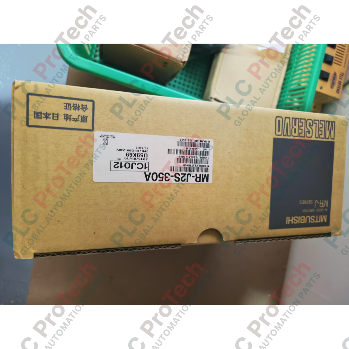
| Model / Part Number |
MR-J2S-350A |
| Series |
MELSERVO-J2-Super |
| Rated Output Power |
3.5 kW |
| Input Power Supply |
3-phase 200 VAC to 230 VAC, 50/60 Hz |
| Permissible Voltage Fluctuation |
170 VAC to 253 VAC |
| Permissible Frequency Fluctuation |
Within 5% |
| Control Method |
Sinusoidal PWM control / current control system |
| Dynamic Brake |
Built-in |
| Speed Frequency Response |
550 Hz or higher |
| Interface Type |
Universal digital pulse / analog input |
| Operating Ambient Temperature |
0 to 55 degC (non-freezing) |
| Storage Ambient Temperature |
-20 to 65 degC (non-freezing) |
| Country of Origin |
Japan |
| Shipping Weight (Calculated) |
3.5 kg |
Connections and Interfaces
| Connector / Terminal |
Functional Assignment / Description |
| CN1A & CN1B |
I/O signal connector block (analog command inputs, high-speed pulse train interfaces, digital control inputs/outputs) |
| CN2 |
Encoder connection port (high-speed serial feedback communication link from the motor encoder) |
| CN3 |
RS-232C / RS-422 communications port (link for PC connection via MR Configurator software) |
| L1, L2, L3 |
Main circuit 3-phase AC 200-230V power supply input terminals |
| L11, L21 |
Control circuit single-phase AC 200-230V auxiliary power supply inputs |
| U, V, W |
3-phase servo motor output terminal connections |
Empirical Engineering Insights
Alternative Models & Compatibility
The MR-J2S-350A utilizes a general-purpose interface. It is distinct from the MR-J2S-350B, which operates on the proprietary SSCNET bus and cannot accept direct pulse train or analog speed commands. When replacing an older MR-J2-350A model, the mechanical footprint is identical, but ensure that parameter file structures are verified using MR Configurator software, as older firmware blocks may define dynamic acceleration limits slightly differently.
Application Pitfalls & Engineering Notes
Under cyclic braking loads with high inertia ratios, the internal dynamic braking circuit might experience thermal saturation. If the servo drive triggers an AL.30 (Regenerative Error) during rapid deceleration, do not bypass the alarm parameters. Instead, install an external, properly sized regenerative braking resistor bank across terminals P and D, ensuring the internal short-circuit bar between PR and PX is removed first.
Commissioning & Wiring Tips
To prevent electromagnetic noise injection into sensitive control lines, separate the CN1A/CN1B signal wires from the high-voltage U, V, and W motor power lines by at least 30 cm. Always ground the motor casing directly to the drive's protective earth terminal using a heavy-duty copper braid, and verify that shielding on the CN2 encoder feedback line is grounded at the drive-side connector casing only.
Installation Guidelines
CRITICAL SAFETY WARNING
Before commencing installation or maintenance, completely de-energize the main line circuit breaker. Wait a minimum of 15 minutes to allow internal high-voltage DC bus capacitors to fully discharge. Always measure the DC bus voltage between terminals P and N with an appropriate multimeter to ensure the potential has dropped below 50 VDC before handling power terminals.
1
Mount the servo drive vertically inside an IP54 or higher rated control cabinet, ensuring there is a minimum cooling clearance of 40 mm above and below the chassis.
2
Connect the single-phase AC control auxiliary power input to L11 and L21 to preserve internal diagnostic displays and warning sequences when main power is disengaged.
3
Wire the 3-phase main power supply lines directly to L1, L2, and L3 through an appropriate magnetic contactor and high-speed semiconductor fuses.
4
Ensure terminal block screws are torqued strictly according to manufacturer specifications (typically 1.2 N-m to 1.5 N-m) to prevent electrical resistance heating and arc flash risks.