


Implementing 3-Switch XOR Ladder Logic with Internal Bit
Implement a 3-SPST switch XOR light circuit in LogixPro or RSLogix 500 using an internal relay bit. Includes truth tables, boolean equations, and verified.

Engineered for precise speed, torque, and position control in heavy industrial environments, the Mitsubishi Electric MR-J3-500A4 is a high-performance digital servo amplifier belonging to the MELSERVO MR-J3 product family. This unit operates on a 400V class grid and is optimized for managing brushless servo motors with continuous current requirements of up to 14.0 A. Incorporating advanced real-time auto-tuning and vibration suppression filters, this amplifier ensures high response levels while suppressing mechanical resonance on critical axes.
| Parameter | Technical Specification |
|---|---|
| Manufacturer | Mitsubishi Electric |
| Model Code | MR-J3-500A4 |
| Product Series | MELSERVO MR-J3 Series |
| Main Circuit Power Supply | 3-phase 380 to 480 VAC, 50/60 Hz |
| Permissible Voltage Fluctuation | 3-phase 323 to 528 VAC |
| Main Circuit Rated Current | 10.8 A |
| Control Circuit Power Supply | 1-phase 380 to 480 VAC, 50/60 Hz |
| Control Circuit Rated Current | 0.2 A |
| Control Circuit Power Consumption | 45 W |
| Rated Output Voltage | 3-phase 323 VAC |
| Rated Output Current | 14.0 A |
| Dynamic Brake | Built-in |
| Cooling System | Force-cooling (integrated cooling fan) |
| Net Weight | 4.6 kg |
| Shipping Weight (Calculated) | 6.0 kg |
| Terminal / Connector | Function / Circuit Assignment |
|---|---|
| L1, L2, L3 | Main circuit 3-phase AC power input |
| L11, L21 | Control circuit 1-phase AC power input |
| U, V, W | Servo motor power output terminals |
| CN1 | General-purpose analog / pulse train I/O interface |
| CN2 | High-resolution encoder feedback input |
| CN3 | PC connection or parameter setup unit interface |
The MR-J3-500A4 is the general-purpose, non-networked analog/pulse-train variant within the MR-J3 400V series. Please note that it cannot directly replace the MR-J3-500B4, which is built exclusively for the SSCNET III optical fiber network. Ensure controller-side interface compatibility before deployment.
Due to the high thermal dissipation profile under continuous heavy load conditions, cabinet designers must ensure a minimum of 40 mm vertical clearing space above and below the amplifier. If installing multiple amplifiers adjacently in an enclosed panel, maintain an ambient operating temperature below 55 degC to prevent premature overtemperature trips.
To prevent high-frequency electro-magnetic interference (EMI) originating from the PWM inverter output, ensure the motor feed cables are properly shielded and grounded to the common baseplate. Additionally, control line cabling on the CN1 connector must use shielded, twisted-pair lines separated from the primary high-power wiring.
Before beginning installation, service, or wiring procedures, isolate and de-energize all primary input and control voltages. Wait a minimum of 15 minutes to allow internal high-voltage DC bus capacitors to discharge to a safe level. Verify with a calibrated multimeter that DC bus voltage is zero before making physical terminal contacts.
Global Express Shipping
Returns & Warranty


Manufacturer: Mitsubishi Electric
Product No.: MR-J3-500A4
Country of origin:United States
Product Type: Servo Amplifiers
Payment: T/T, Western Union
Weight: 4600g
Shipping port: Xiamen
Warranty: 12 months
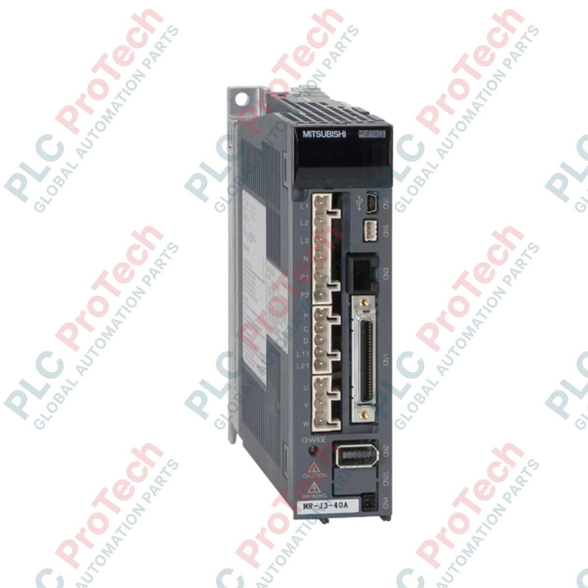
Engineered for precise speed, torque, and position control in heavy industrial environments, the Mitsubishi Electric MR-J3-500A4 is a high-performance digital servo amplifier belonging to the MELSERVO MR-J3 product family. This unit operates on a 400V class grid and is optimized for managing brushless servo motors with continuous current requirements of up to 14.0 A. Incorporating advanced real-time auto-tuning and vibration suppression filters, this amplifier ensures high response levels while suppressing mechanical resonance on critical axes.
| Parameter | Technical Specification |
|---|---|
| Manufacturer | Mitsubishi Electric |
| Model Code | MR-J3-500A4 |
| Product Series | MELSERVO MR-J3 Series |
| Main Circuit Power Supply | 3-phase 380 to 480 VAC, 50/60 Hz |
| Permissible Voltage Fluctuation | 3-phase 323 to 528 VAC |
| Main Circuit Rated Current | 10.8 A |
| Control Circuit Power Supply | 1-phase 380 to 480 VAC, 50/60 Hz |
| Control Circuit Rated Current | 0.2 A |
| Control Circuit Power Consumption | 45 W |
| Rated Output Voltage | 3-phase 323 VAC |
| Rated Output Current | 14.0 A |
| Dynamic Brake | Built-in |
| Cooling System | Force-cooling (integrated cooling fan) |
| Net Weight | 4.6 kg |
| Shipping Weight (Calculated) | 6.0 kg |
| Terminal / Connector | Function / Circuit Assignment |
|---|---|
| L1, L2, L3 | Main circuit 3-phase AC power input |
| L11, L21 | Control circuit 1-phase AC power input |
| U, V, W | Servo motor power output terminals |
| CN1 | General-purpose analog / pulse train I/O interface |
| CN2 | High-resolution encoder feedback input |
| CN3 | PC connection or parameter setup unit interface |
The MR-J3-500A4 is the general-purpose, non-networked analog/pulse-train variant within the MR-J3 400V series. Please note that it cannot directly replace the MR-J3-500B4, which is built exclusively for the SSCNET III optical fiber network. Ensure controller-side interface compatibility before deployment.
Due to the high thermal dissipation profile under continuous heavy load conditions, cabinet designers must ensure a minimum of 40 mm vertical clearing space above and below the amplifier. If installing multiple amplifiers adjacently in an enclosed panel, maintain an ambient operating temperature below 55 degC to prevent premature overtemperature trips.
To prevent high-frequency electro-magnetic interference (EMI) originating from the PWM inverter output, ensure the motor feed cables are properly shielded and grounded to the common baseplate. Additionally, control line cabling on the CN1 connector must use shielded, twisted-pair lines separated from the primary high-power wiring.
Before beginning installation, service, or wiring procedures, isolate and de-energize all primary input and control voltages. Wait a minimum of 15 minutes to allow internal high-voltage DC bus capacitors to discharge to a safe level. Verify with a calibrated multimeter that DC bus voltage is zero before making physical terminal contacts.
Global Express Shipping
Returns & Warranty
Orders are processed and delivered Monday-Friday (excluding public holidays).
For full eligibility, restocking fees, and international return details, please view our official Refund & Return Policy .
| Country of origin |
United States
|

Implement a 3-SPST switch XOR light circuit in LogixPro or RSLogix 500 using an internal relay bit. Includes truth tables, boolean equations, and verified.

Integrate Allen-Bradley CompactLogix, Caterpillar ATS, and generators into DeltaV DCS over Modbus RTU. Covers ProSoft MVI69-MCM, Miille DIN266 gateways.

ONS instruction fires but the OTE coil never latches in Studio 5000 because the one-shot is only true for one scan. Use OTL/OTU or seal-in logic instead.

Configure Allen-Bradley Kinetix 5500 servo drives on EtherNet/IP. Covers CIP Sync, IEEE 1588 V2 timing, Stratix selection, DLR topology, and HMI.

A moving-average filter is the sliding-window smoother most instrument engineers drop into DCS and PLC analog paths. Here is how the window works, how N and sample time set lag, and when a...

On Frame 5–9 gas turbines, GE Mark VI and Mark VIe run control as function-block application software. This article maps process, protection, and sequencing functions—and what Toolbox ST access...