


Implementing 3-Switch XOR Ladder Logic with Internal Bit
Implement a 3-SPST switch XOR light circuit in LogixPro or RSLogix 500 using an internal relay bit. Includes truth tables, boolean equations, and verified.

Integrating seamlessly into high-precision industrial motion networks, this Mitsubishi Electric MR-JS2-200A dynamic drive provides precise closed-loop speed, torque, and position control for compatible AC rotary servo motors. Designed with an analog and pulse train interface, this 2.0 kW capacity servo amplifier is optimized for rapid-response positioning tasks in robust automation systems. It employs advanced real-time adaptive tuning algorithms to minimize tracking errors and handle fluctuating mechanical loads without manual intervention.
| Technical Specification | Value |
|---|---|
| Manufacturer | Mitsubishi Electric |
| Model Reference | MR-JS2-200A |
| Control Interface Type | Type A (General-Purpose Analog / Pulse Train) |
| Output Rated Power | 2.0 kW (2000 Watts) |
| Input Voltage Phase | 3-Phase AC |
| Input Rated Voltage | 200 to 230 VAC |
| Input Rated Current | 10.5 A |
| Input Frequency Range | 50 / 60 Hz |
| Ambient Operating Temperature | 0 to 55 degC (non-freezing) |
| Shipping Weight (Calculated) | 5.0 kg |
| Country of Origin | Japan |
| Terminal / Connector Block | Circuit Assignment & Function |
|---|---|
| L1, L2, L3 | Main AC Power Supply Input (3-Phase 200-230VAC) |
| U, V, W | Servo Motor Power Output (3-Phase AC Variable Frequency) |
| P, D, C | Regenerative Resistor Option Terminals (P-D Shorted for Internal Resistor) |
| CN1A / CN1B | Analog Commands, Pulse-Train Control Input, and Digital I/O Signals |
| CN2 | Encoder Feedback Connection (Serial Communications) |
This amplifier belongs to the classical general-purpose interface lineup. If you are converting systems from SSCNET network-based control (Type B), ensure command source modifications are carried out on your PLC software. For replacements of older MR-J2S-200A series drives, confirm your mounting footprints and cable terminations are clean and dry, as connector pinout configurations remain highly compatible but terminal spacing can differ slightly across specific enclosure versions.
Operating high-inertia loads at fast cycle rates can exceed the internal regenerative braking capacity of the amplifier. Monitor diagnostic parameters closely for AL.30 (Regenerative Error) or AL.33 (Overvoltage) faults. If these trigger, disconnect the terminal link between P and D and interface a properly rated external regenerative brake option across P and C. Ensure thermal space constraints of 40mm above and below the drive are maintained inside unventilated electrical cabinets.
Always route high-voltage lines (L1/L2/L3 and U/V/W) in separate wire ducts from low-voltage signal lines (CN1A/CN1B and CN2) to mitigate electro-magnetic coupling. Always construct encoder signal wires using braided shielded twisted-pair cables, and terminate the shield directly to the CN2 connector shell. Ground the amplifier chassis using a low-impedance copper strap to a single-point system ground plate.
Ensure all input AC power is completely disconnected and locked out prior to terminal modifications. Wait at least 15 minutes after power-down for internal high-voltage DC bus capacitors to discharge to a safe level (under 20V) before initiating wire service or internal inspections.
Mount the amplifier vertically on flat, rigid sheet metal panels, ensuring non-obstructed ventilation paths.
Secure the ground conductor (PE) to the protective earth terminal prior to connecting power or motor cabling.
Plug in the high-density CN1 control and CN2 encoder feedback plugs, hand-tightening the connector screws.
Apply input control power first to verify drive parameter settings via serial setup software before running mains power.
Global Express Shipping
Returns & Warranty


Manufacturer: Mitsubishi Electric
Product No.: MR-JS2-200A
Country of origin:United States
Product Type: Servo AC Amplifiers
Payment: T/T, Western Union
Weight: 5000g
Shipping port: Xiamen
Warranty: 12 months
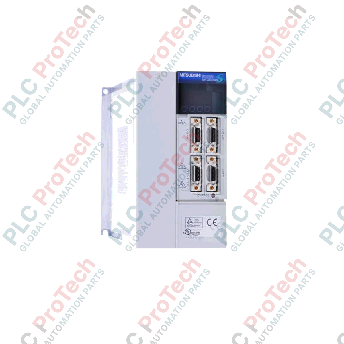
Integrating seamlessly into high-precision industrial motion networks, this Mitsubishi Electric MR-JS2-200A dynamic drive provides precise closed-loop speed, torque, and position control for compatible AC rotary servo motors. Designed with an analog and pulse train interface, this 2.0 kW capacity servo amplifier is optimized for rapid-response positioning tasks in robust automation systems. It employs advanced real-time adaptive tuning algorithms to minimize tracking errors and handle fluctuating mechanical loads without manual intervention.
| Technical Specification | Value |
|---|---|
| Manufacturer | Mitsubishi Electric |
| Model Reference | MR-JS2-200A |
| Control Interface Type | Type A (General-Purpose Analog / Pulse Train) |
| Output Rated Power | 2.0 kW (2000 Watts) |
| Input Voltage Phase | 3-Phase AC |
| Input Rated Voltage | 200 to 230 VAC |
| Input Rated Current | 10.5 A |
| Input Frequency Range | 50 / 60 Hz |
| Ambient Operating Temperature | 0 to 55 degC (non-freezing) |
| Shipping Weight (Calculated) | 5.0 kg |
| Country of Origin | Japan |
| Terminal / Connector Block | Circuit Assignment & Function |
|---|---|
| L1, L2, L3 | Main AC Power Supply Input (3-Phase 200-230VAC) |
| U, V, W | Servo Motor Power Output (3-Phase AC Variable Frequency) |
| P, D, C | Regenerative Resistor Option Terminals (P-D Shorted for Internal Resistor) |
| CN1A / CN1B | Analog Commands, Pulse-Train Control Input, and Digital I/O Signals |
| CN2 | Encoder Feedback Connection (Serial Communications) |
This amplifier belongs to the classical general-purpose interface lineup. If you are converting systems from SSCNET network-based control (Type B), ensure command source modifications are carried out on your PLC software. For replacements of older MR-J2S-200A series drives, confirm your mounting footprints and cable terminations are clean and dry, as connector pinout configurations remain highly compatible but terminal spacing can differ slightly across specific enclosure versions.
Operating high-inertia loads at fast cycle rates can exceed the internal regenerative braking capacity of the amplifier. Monitor diagnostic parameters closely for AL.30 (Regenerative Error) or AL.33 (Overvoltage) faults. If these trigger, disconnect the terminal link between P and D and interface a properly rated external regenerative brake option across P and C. Ensure thermal space constraints of 40mm above and below the drive are maintained inside unventilated electrical cabinets.
Always route high-voltage lines (L1/L2/L3 and U/V/W) in separate wire ducts from low-voltage signal lines (CN1A/CN1B and CN2) to mitigate electro-magnetic coupling. Always construct encoder signal wires using braided shielded twisted-pair cables, and terminate the shield directly to the CN2 connector shell. Ground the amplifier chassis using a low-impedance copper strap to a single-point system ground plate.
Ensure all input AC power is completely disconnected and locked out prior to terminal modifications. Wait at least 15 minutes after power-down for internal high-voltage DC bus capacitors to discharge to a safe level (under 20V) before initiating wire service or internal inspections.
Mount the amplifier vertically on flat, rigid sheet metal panels, ensuring non-obstructed ventilation paths.
Secure the ground conductor (PE) to the protective earth terminal prior to connecting power or motor cabling.
Plug in the high-density CN1 control and CN2 encoder feedback plugs, hand-tightening the connector screws.
Apply input control power first to verify drive parameter settings via serial setup software before running mains power.
Global Express Shipping
Returns & Warranty
Orders are processed and delivered Monday-Friday (excluding public holidays).
For full eligibility, restocking fees, and international return details, please view our official Refund & Return Policy .
| Country of origin |
United States
|

Implement a 3-SPST switch XOR light circuit in LogixPro or RSLogix 500 using an internal relay bit. Includes truth tables, boolean equations, and verified.

Integrate Allen-Bradley CompactLogix, Caterpillar ATS, and generators into DeltaV DCS over Modbus RTU. Covers ProSoft MVI69-MCM, Miille DIN266 gateways.

ONS instruction fires but the OTE coil never latches in Studio 5000 because the one-shot is only true for one scan. Use OTL/OTU or seal-in logic instead.

Configure Allen-Bradley Kinetix 5500 servo drives on EtherNet/IP. Covers CIP Sync, IEEE 1588 V2 timing, Stratix selection, DLR topology, and HMI.

A moving-average filter is the sliding-window smoother most instrument engineers drop into DCS and PLC analog paths. Here is how the window works, how N and sample time set lag, and when a...

On Frame 5–9 gas turbines, GE Mark VI and Mark VIe run control as function-block application software. This article maps process, protection, and sequencing functions—and what Toolbox ST access...