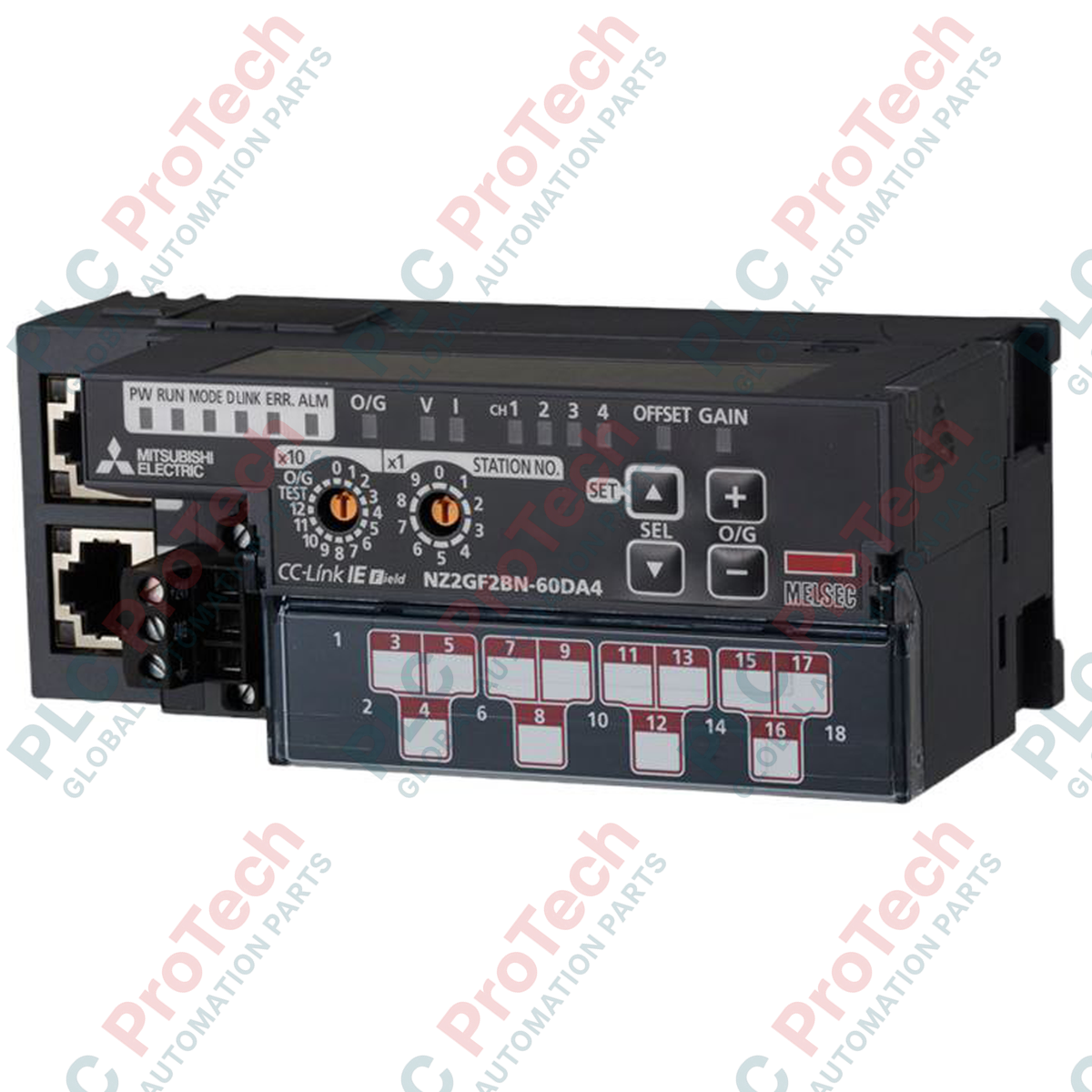
Facilitating high-speed digital-to-analog conversion within CC-Link IE Field networks, the Mitsubishi Electric NZ2GF2BN-60DA4 serves as a high-precision remote device station featuring four independent analog output channels. This module converts 16-bit signed binary digital values into precise voltage or current signals to drive field actuators, control valves, and speed regulators in complex industrial automation architectures.
Key Features
-
Four High-Resolution Channels: Supports independent configuration for voltage (-10 to 10 VDC) or current (0 to 20 mADC) outputs.
-
Robust Signal Isolation: Features photocoupler isolation between the communication system and analog outputs, alongside transformer isolation between the power supply and analog circuits.
-
Output Short-Circuit Protection: Integrated protection circuitry prevents module damage from field wiring faults or shorted loads.
-
Flexible Network Topology: Dual RJ45 ports support line, star, and ring topologies on CC-Link IE Field networks.
-
Removable Terminal Block: Two-piece 18-point terminal block simplifies pre-wiring, commissioning, and hot-swapping procedures.
Industrial Applications
- Proportional control valve positioning in hydraulic and pneumatic systems.
- Speed reference distribution to variable frequency drives (VFDs).
- Setpoint transmission to SCR power controllers in industrial heating applications.
- Remote signal generation for paper, steel, and textile tension control systems.
Technical Specifications
| Parameter |
Specification |
| Manufacturer |
Mitsubishi Electric |
| Model Number |
NZ2GF2BN-60DA4 |
| Product Type |
Main D/A Converter Module |
| Station Type |
Remote device station |
| Analog Output Channels |
4 channels (4 points) |
| Digital Input Resolution |
16-bit signed binary (-16384 to 16383, -288 to 12287, -12288 to 12287) |
| Voltage Output Range |
-10 to 10 VDC (External load: 1k ohm to 1M ohm) |
| Current Output Range |
0 to 20 mADC (External load: 0 ohm to 600 ohm) |
| Output Protection |
Short-circuit protected |
| Isolation (Comm to Analog) |
Photocoupler isolation |
| Isolation (Power to Analog) |
Transformer isolation |
| Isolation (Channel to Channel) |
Non-isolated |
| Withstand Voltage |
500 VAC for 1 minute (between power/comm and analog outputs) |
| Communication Interface |
RJ45 connector (CC-Link IE Field) |
| Power Supply Terminal |
M2.5 screw terminal block (Tightening torque: 0.5 to 0.6 Nm) |
| I/O Terminal Block |
18-point two-piece terminal block, M3 screws (Tightening torque: 0.43 to 0.57 Nm) |
| Module Weight |
0.29 kg |
| Shipping Weight (Calculated) |
1.50 kg |
Connections and Interfaces
| Interface Type |
Terminal / Pin Assignment |
Functional Assignment |
| RJ45 Ports |
PORT1 / PORT2 |
CC-Link IE Field Network connection (supports line/ring topologies) |
| Power Terminal Block |
24V, 0V, FG |
Module 24 VDC power input and Frame Ground |
| 18-Point Terminal Block |
V+, I+, COM (Channels 1 to 4) |
Analog voltage/current outputs and common reference lines |
Alternative Models & Compatibility
The NZ2GF2BN-60DA4 is specifically designed for CC-Link IE Field networks and is not compatible with legacy CC-Link or CC-Link IE Field Basic protocols. Ensure that the master station PLC is equipped with a compatible CC-Link IE Field Master/Local module (such as the RJ71GF11-T2 or QJ71GF11-T2) and that the correct CSP+ profile is registered in GX Works2 or GX Works3 prior to network configuration.
Application Pitfalls & Engineering Notes
Because there is no channel-to-channel isolation on this module, all analog output common (COM) terminals are internally tied together. Connecting field devices with differing ground potentials can create ground loops, resulting in signal drift, measurement errors, or hardware degradation. If channel-to-channel isolation is required by your application, external signal isolators must be installed between the module outputs and the field devices.
Commissioning & Wiring Tips
Always use high-quality double-shielded twisted-pair cables for analog signal runs. Ground the shield at only one end (typically the control panel side) to prevent ground loop currents. Ensure the Frame Ground (FG) terminal on the power supply block is connected to a dedicated class-D ground (100 ohms or less) using a minimum of 2 mm2 wire to minimize high-frequency noise interference from adjacent variable frequency drives.
Installation Guidelines
CRITICAL WARNING: Prior to commencing any installation, wiring, or maintenance activities, ensure all incoming AC and DC power sources to the control panel are completely de-energized. Verify the absence of voltage using a calibrated digital multimeter. Failure to isolate power can result in severe electrical shock, equipment destruction, or erratic control system behavior.
1
Mount the module securely to a 35mm DIN rail, ensuring the DIN rail hook is locked in place.
2
Connect the CC-Link IE Field Ethernet cables to PORT1 and PORT2, ensuring the RJ45 connectors click firmly into position.
3
Wire the 24VDC module power supply and FG to the dedicated M2.5 terminal block, tightening to the specified torque of 0.5 to 0.6 Nm.
4
Connect the analog output signal wires to the 18-point removable terminal block, ensuring M3 screws are torqued to 0.43 to 0.57 Nm, then plug the block securely into the module.