


Implementing 3-Switch XOR Ladder Logic with Internal Bit
Implement a 3-SPST switch XOR light circuit in LogixPro or RSLogix 500 using an internal relay bit. Includes truth tables, boolean equations, and verified.

Designed for high-precision thermal regulation within industrial automation architectures, the Q64TCTTBW serves as a dedicated multi-channel temperature control module for the Mitsubishi Electric MELSEC-Q Series PLC platform. This module integrates PID control loops directly with thermocouple sensor interfaces to provide stable, real-time temperature regulation without overloading the main PLC CPU.
The unit supports four channels of thermocouple inputs and features integrated heater disconnection detection (indicated by the "BW" designation), which utilizes external current transformers (CTs) to monitor load currents and quickly identify heating element failures. This capability is vital for packaging machinery, plastics extrusion, semiconductor manufacturing, and environmental chambers where thermal stability and heating element integrity are critical.
| Manufacturer | Mitsubishi Electric |
| Model / Part Number | Q64TCTTBW |
| Series | MELSEC-Q Series |
| Module Type | Temperature Control Module (with Heater Disconnection Detection) |
| Control Channels | 4 Channels |
| Input Sensor Type | Thermocouple (K, J, T, B, S, E, R, N) |
| Indication Accuracy | Plus/minus 0.3% of full scale (at ambient temperature of 25 degC plus/minus 5 degC) |
| Sampling Period | 0.5 seconds for all 4 channels |
| Control Output | Transistor (Sink) output, 24V DC, 100mA/point |
| Heater Disconnection Detection | Supported (requires external current transformer, sold separately) |
| Internal Current Consumption (5V DC) | 0.55 A |
| External Connections | 18-point terminal block |
When installing the module on a MELSEC-Q series base unit, ensure the system power supply is completely switched off to prevent electrical shock or module damage. Align the module's bottom guide lug with the base unit slot, push the module firmly into place, and secure the module fixing screw (M3 x 12) to a torque of 0.36 to 0.48 N-m.
To minimize electromagnetic interference, route thermocouple input cables and Current Transformer (CT) leads separately from high-voltage AC power lines and motor drive cables. Utilize shielded cables for sensor runs and ensure proper grounding configurations are maintained.
Global Express Shipping
Returns & Warranty


Manufacturer: Mitsubishi Electric
Product No.: Q64TCTTBW
Country of origin:United States
Product Type: Temperature Control Modules
Payment: T/T, Western Union
Weight: 1300g
Shipping port: Xiamen
Warranty: 12 months
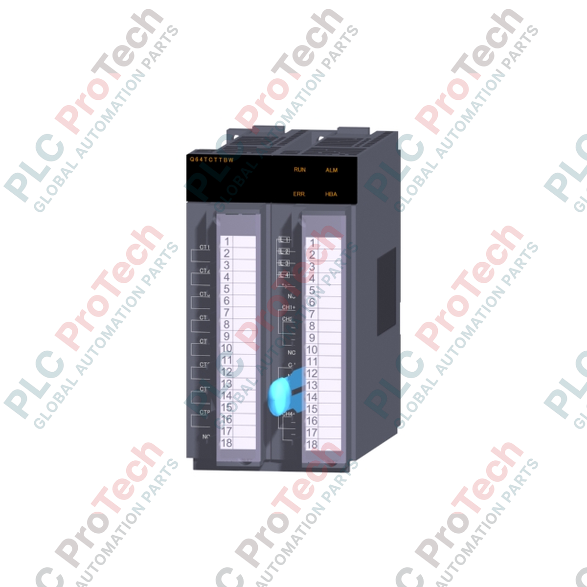
Designed for high-precision thermal regulation within industrial automation architectures, the Q64TCTTBW serves as a dedicated multi-channel temperature control module for the Mitsubishi Electric MELSEC-Q Series PLC platform. This module integrates PID control loops directly with thermocouple sensor interfaces to provide stable, real-time temperature regulation without overloading the main PLC CPU.
The unit supports four channels of thermocouple inputs and features integrated heater disconnection detection (indicated by the "BW" designation), which utilizes external current transformers (CTs) to monitor load currents and quickly identify heating element failures. This capability is vital for packaging machinery, plastics extrusion, semiconductor manufacturing, and environmental chambers where thermal stability and heating element integrity are critical.
| Manufacturer | Mitsubishi Electric |
| Model / Part Number | Q64TCTTBW |
| Series | MELSEC-Q Series |
| Module Type | Temperature Control Module (with Heater Disconnection Detection) |
| Control Channels | 4 Channels |
| Input Sensor Type | Thermocouple (K, J, T, B, S, E, R, N) |
| Indication Accuracy | Plus/minus 0.3% of full scale (at ambient temperature of 25 degC plus/minus 5 degC) |
| Sampling Period | 0.5 seconds for all 4 channels |
| Control Output | Transistor (Sink) output, 24V DC, 100mA/point |
| Heater Disconnection Detection | Supported (requires external current transformer, sold separately) |
| Internal Current Consumption (5V DC) | 0.55 A |
| External Connections | 18-point terminal block |
When installing the module on a MELSEC-Q series base unit, ensure the system power supply is completely switched off to prevent electrical shock or module damage. Align the module's bottom guide lug with the base unit slot, push the module firmly into place, and secure the module fixing screw (M3 x 12) to a torque of 0.36 to 0.48 N-m.
To minimize electromagnetic interference, route thermocouple input cables and Current Transformer (CT) leads separately from high-voltage AC power lines and motor drive cables. Utilize shielded cables for sensor runs and ensure proper grounding configurations are maintained.
Global Express Shipping
Returns & Warranty
Orders are processed and delivered Monday-Friday (excluding public holidays).
For full eligibility, restocking fees, and international return details, please view our official Refund & Return Policy .
| Country of origin |
United States
|

Implement a 3-SPST switch XOR light circuit in LogixPro or RSLogix 500 using an internal relay bit. Includes truth tables, boolean equations, and verified.

Integrate Allen-Bradley CompactLogix, Caterpillar ATS, and generators into DeltaV DCS over Modbus RTU. Covers ProSoft MVI69-MCM, Miille DIN266 gateways.

ONS instruction fires but the OTE coil never latches in Studio 5000 because the one-shot is only true for one scan. Use OTL/OTU or seal-in logic instead.

Configure Allen-Bradley Kinetix 5500 servo drives on EtherNet/IP. Covers CIP Sync, IEEE 1588 V2 timing, Stratix selection, DLR topology, and HMI.

A moving-average filter is the sliding-window smoother most instrument engineers drop into DCS and PLC analog paths. Here is how the window works, how N and sample time set lag, and when a...

On Frame 5–9 gas turbines, GE Mark VI and Mark VIe run control as function-block application software. This article maps process, protection, and sequencing functions—and what Toolbox ST access...