


Implementing 3-Switch XOR Ladder Logic with Internal Bit
Implement a 3-SPST switch XOR light circuit in LogixPro or RSLogix 500 using an internal relay bit. Includes truth tables, boolean equations, and verified.

Engineered for high-density industrial control architectures, this 64-point digital output module provides high-speed, reliable transistor switching within the MELSEC iQ-R Series PLC platform. The Mitsubishi Electric RY42NT2P acts as a robust NPN sink-type transistor interface, featuring built-in overcurrent and thermal overload protection to shield critical field circuits and internal hardware from electrical faults. Its ultra-compact dual 40-pin connector layout maximizes I/O density in heavy-duty automation panels while maintaining precise response times.
| Parameter | Specification |
|---|---|
| Manufacturer | Mitsubishi Electric |
| Model Number | RY42NT2P |
| PLC Series | MELSEC iQ-R |
| Module Type | Transistor Output Module |
| Number of Outputs | 64 points |
| Output Type | Transistor (Sink / NPN) |
| Rated Load Voltage | 12 to 24 VDC (+10% / -15%) |
| Max. Load Current | 0.2 A per point, 1.6 A per common |
| Response Time (Off to On) | <= 1.0 ms |
| Response Time (On to Off) | <= 1.5 ms |
| Internal Current Consumption | 110 mA (5 VDC) |
| Physical Connection | Dual 40-pin connectors |
| Protection Functions | Overcurrent protection, thermal shutdown protection |
| Weight | 0.13 kg |
| Shipping Weight (Calculated) | 1.50 kg |
| Country of Origin | Japan |
When migrating legacy systems or processing system upgrades, note that the RY42NT2P replaces older non-protected 64-point output modules. The "P" version incorporates hardware-level self-resetting protection circuits, which might slightly alter thermal dissipation profiles in extremely cramped, unventilated enclosures. Confirm your firmware configuration in GX Works3 matches the exact "P" designation to enable diagnostics for channel-specific overcurrent flags.
While the module is rated for 0.2 A per point, the aggregate current limit of 1.6 A per common group must not be exceeded. In installations running simultaneous high-duty inductive loads, such as large solenoids or direct-drive miniature relays, external flyback/freewheeling diodes must be placed across the loads. Failure to suppress inductive kickback will lead to premature fatigue of the internal output transistors and transient noise injection into the PLC backplane.
Always utilize standard pre-assembled 40-pin ribbon cable systems or dedicated terminal block conversion modules (e.g., terminal breakout boards) to eliminate manual connector-soldering errors. To minimize electromagnetic interference (EMI), route your 24 VDC field power supply lines in pathways separate from high-power AC motor drives and motor cabling.
Align the module's lower hook with the slot on the base unit, making sure the connector pins are clear of obstruction.
Push the module firmly toward the base unit until it clicks securely into place, ensuring the module mounting lever engages properly.
Tighten the module fixing screw (if used in high-vibration environments) to the specified OEM torque limits.
Connect the 40-pin terminal harnesses securely, ensuring the locking mechanisms click into position to prevent loose physical contacts.
Global Express Shipping
Returns & Warranty


Manufacturer: Mitsubishi Electric
Product No.: RY42NT2P
Country of origin:United States
Product Type: PLC Output Modules
Payment: T/T, Western Union
Weight: 130g
Shipping port: Xiamen
Warranty: 12 months
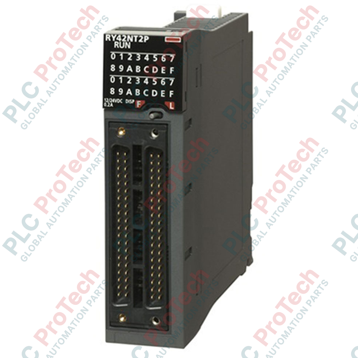
Engineered for high-density industrial control architectures, this 64-point digital output module provides high-speed, reliable transistor switching within the MELSEC iQ-R Series PLC platform. The Mitsubishi Electric RY42NT2P acts as a robust NPN sink-type transistor interface, featuring built-in overcurrent and thermal overload protection to shield critical field circuits and internal hardware from electrical faults. Its ultra-compact dual 40-pin connector layout maximizes I/O density in heavy-duty automation panels while maintaining precise response times.
| Parameter | Specification |
|---|---|
| Manufacturer | Mitsubishi Electric |
| Model Number | RY42NT2P |
| PLC Series | MELSEC iQ-R |
| Module Type | Transistor Output Module |
| Number of Outputs | 64 points |
| Output Type | Transistor (Sink / NPN) |
| Rated Load Voltage | 12 to 24 VDC (+10% / -15%) |
| Max. Load Current | 0.2 A per point, 1.6 A per common |
| Response Time (Off to On) | <= 1.0 ms |
| Response Time (On to Off) | <= 1.5 ms |
| Internal Current Consumption | 110 mA (5 VDC) |
| Physical Connection | Dual 40-pin connectors |
| Protection Functions | Overcurrent protection, thermal shutdown protection |
| Weight | 0.13 kg |
| Shipping Weight (Calculated) | 1.50 kg |
| Country of Origin | Japan |
When migrating legacy systems or processing system upgrades, note that the RY42NT2P replaces older non-protected 64-point output modules. The "P" version incorporates hardware-level self-resetting protection circuits, which might slightly alter thermal dissipation profiles in extremely cramped, unventilated enclosures. Confirm your firmware configuration in GX Works3 matches the exact "P" designation to enable diagnostics for channel-specific overcurrent flags.
While the module is rated for 0.2 A per point, the aggregate current limit of 1.6 A per common group must not be exceeded. In installations running simultaneous high-duty inductive loads, such as large solenoids or direct-drive miniature relays, external flyback/freewheeling diodes must be placed across the loads. Failure to suppress inductive kickback will lead to premature fatigue of the internal output transistors and transient noise injection into the PLC backplane.
Always utilize standard pre-assembled 40-pin ribbon cable systems or dedicated terminal block conversion modules (e.g., terminal breakout boards) to eliminate manual connector-soldering errors. To minimize electromagnetic interference (EMI), route your 24 VDC field power supply lines in pathways separate from high-power AC motor drives and motor cabling.
Align the module's lower hook with the slot on the base unit, making sure the connector pins are clear of obstruction.
Push the module firmly toward the base unit until it clicks securely into place, ensuring the module mounting lever engages properly.
Tighten the module fixing screw (if used in high-vibration environments) to the specified OEM torque limits.
Connect the 40-pin terminal harnesses securely, ensuring the locking mechanisms click into position to prevent loose physical contacts.
Global Express Shipping
Returns & Warranty
Orders are processed and delivered Monday-Friday (excluding public holidays).
For full eligibility, restocking fees, and international return details, please view our official Refund & Return Policy .
| Country of origin |
United States
|

Implement a 3-SPST switch XOR light circuit in LogixPro or RSLogix 500 using an internal relay bit. Includes truth tables, boolean equations, and verified.

Integrate Allen-Bradley CompactLogix, Caterpillar ATS, and generators into DeltaV DCS over Modbus RTU. Covers ProSoft MVI69-MCM, Miille DIN266 gateways.

ONS instruction fires but the OTE coil never latches in Studio 5000 because the one-shot is only true for one scan. Use OTL/OTU or seal-in logic instead.

Configure Allen-Bradley Kinetix 5500 servo drives on EtherNet/IP. Covers CIP Sync, IEEE 1588 V2 timing, Stratix selection, DLR topology, and HMI.

A moving-average filter is the sliding-window smoother most instrument engineers drop into DCS and PLC analog paths. Here is how the window works, how N and sample time set lag, and when a...

On Frame 5–9 gas turbines, GE Mark VI and Mark VIe run control as function-block application software. This article maps process, protection, and sequencing functions—and what Toolbox ST access...