Description
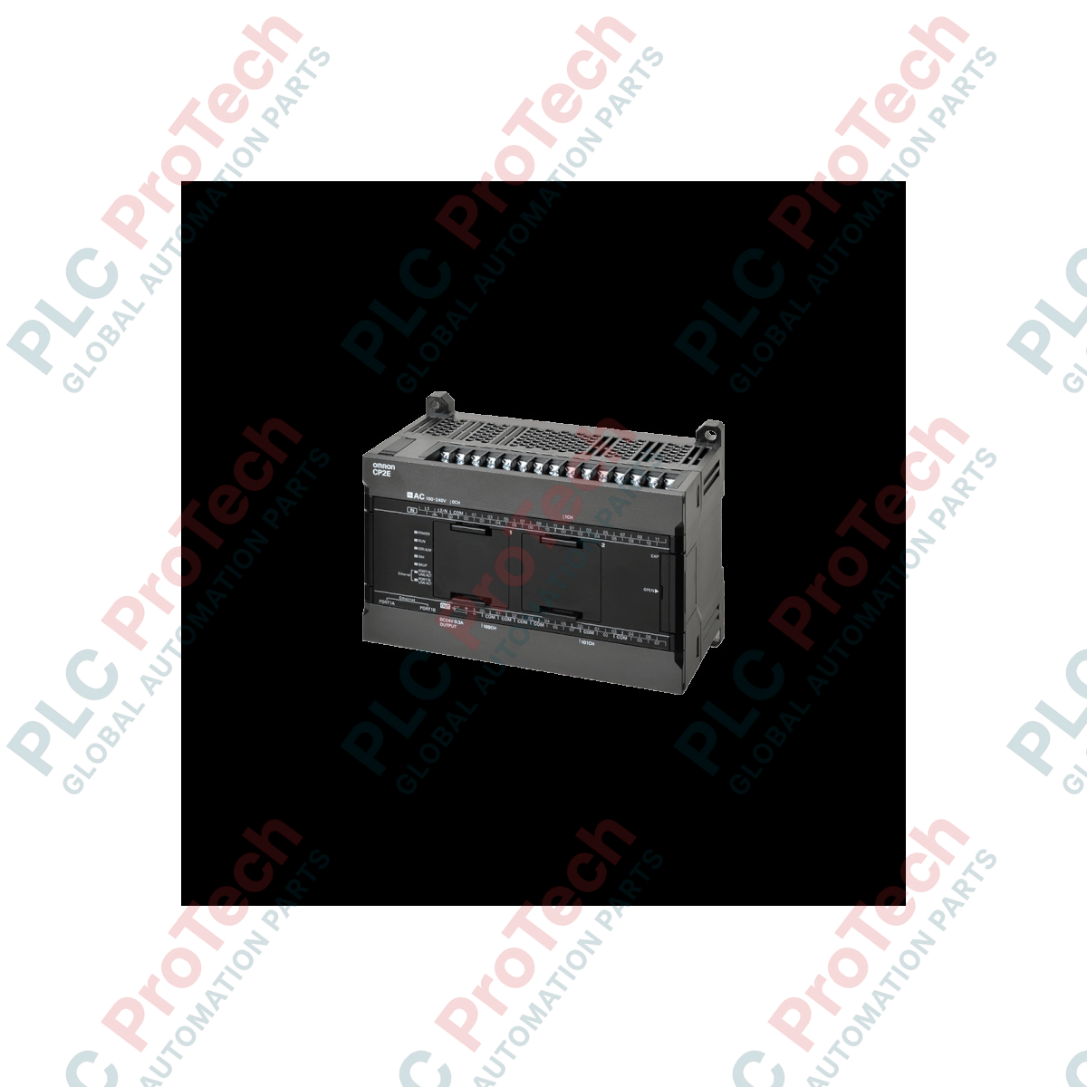
Optimized for decentralized industrial networks, the Omron CP2E-N40DT-D micro-PLC integrates essential automation control with native Ethernet capabilities. This controller is designed specifically for machinery setups requiring remote monitoring, multi-node fieldbus communications, and compact footprint configurations. Running on a robust 24 VDC power supply, it features 40 built-in digital I/O points and an integrated dual-port Ethernet switch, drastically reducing wiring complexity and eliminating the need for external network switch hardware.
Key Features
-
Dual Ethernet Ports: Built-in Ethernet switch capabilities supporting Modbus TCP Client/Server and Ethernet/IP communications.
-
High-Density IO: Offers 24 digital inputs (24 VDC) and 16 transistor sinking outputs in a space-saving DIN-rail form factor.
-
Positioning Capabilities: Includes 4 axes of high-speed counter inputs (up to 100 kHz) and 4 axes of pulse outputs for precise motion and positioning control.
-
Battery-Free Operation: Employs high-capacity flash memory to retain program logic and critical system data, reducing preventative maintenance schedules.
-
Extended Temperature Envelope: Engineered to operate reliably across a wide thermal range without requiring active panel cooling.
Applications
-
Packaging & Labeling Machinery: Synchronized feeding, wrapping, and high-speed registration mark detection.
-
Conveyor & Material Handling Systems: Smart routing, decentralized sorting, and sensor-driven lane control via Ethernet/IP.
-
Pumping and Fluid Control: Remote telemetry integration, pressure monitoring, and pump staging protocols.
-
Building Infrastructure & HVAC: Localized air handling unit automation, climate profiles, and Modbus TCP sub-metering.
Technical Specifications
| Parameter |
Technical Value |
| Manufacturer |
Omron Industrial Automation |
| Model Number |
CP2E-N40DT-D |
| Series Type |
CP2E Series (N-Type / Network Model) |
| Supply Voltage |
24 VDC (Acceptable range: 20.4 to 26.4 VDC) |
| Total Built-in I/O |
40 Points (24 Inputs, 16 Outputs) |
| Digital Inputs |
24 points, 24 VDC (Sinking / Sourcing, IEC 61131-2 Type 1 compliant) |
| Digital Outputs |
16 points, Transistor (Sinking) |
| Output Load Capacity |
24 VDC, 0.3 A max per point; 3.6 A max per common terminal |
| Program Capacity |
10,000 steps |
| Data Memory Capacity |
16,000 words |
| Integrated Interfaces |
2x RJ45 Ethernet ports (with internal switch functionality), 1x USB 2.0 (Type-B) |
| Operating Temperature |
-20 to 60 degC |
| Storage Temperature |
-25 to 70 degC |
| Shipping Weight (Calculated) |
0.85 kg |
| Package Dimensions (Calculated) |
165 mm x 125 mm x 100 mm |
Connections and Interfaces
| Terminal / Interface |
Signal / Purpose |
| Power Terminals |
24 VDC (+ / -) & Functional Ground (FG) |
| Input Terminal Block (Top) |
Channels 00 to 11 (High-speed and standard inputs with common terminals) |
| Output Terminal Block (Bottom) |
Channels 00 to 07 (Sinking transistor configurations with shared common grounds) |
| Dual Ethernet Ports (RJ45) |
Integrated switch ports supporting EtherNet/IP and Modbus TCP peer connection |
| USB Port (Type-B) |
Programming, parameterization, and diagnostic monitoring connection |
Empirical Engineering Insights
Alternative Models & Compatibility
The CP2E-N40DT-D serves as a natural upgrade path for legacy CP1E-N40DT-D controllers. When converting programs inside Omron CX-Programmer (version 9.72 or higher), ensure that the target PLC architecture is set correctly to enable access to the expanded memory and advanced function blocks of the CP2E. Please note that while input and output footprint assignments remain identical, the built-in Ethernet settings must be explicitly defined under the CP2E network settings module to initialize the internal Ethernet switch registers.
Application Pitfalls & Engineering Notes
When mounting this unit horizontally within standard control panels, passive heat dissipation is highly efficient. However, if the ambient cabinet temperature exceeds 50 degC, it is critical to de-rate the simultaneous input-on ratio. Specifically, avoid running more than 60% of the inputs simultaneously at 24 VDC to prevent internal optical isolation degradation. Additionally, since the outputs are sinking transistor configurations, external clamp diodes must be installed on inductive loads (such as DC solenoids or relays) to protect the internal transistors from high-voltage flyback transients.
Commissioning & Wiring Tips
The built-in dual RJ45 Ethernet ports function as an internal Ethernet switch and share a single IP address. Do not create physical loops in your Ethernet layout unless utilizing an external managed switch with Rapid Spanning Tree Protocol (RSTP) enabled elsewhere in the network topology. For reliable high-speed counter positioning up to 100 kHz, utilize shielded twisted-pair (STP) cabling for inputs 00 through 03, terminating the shield securely at the panel's star ground block rather than at the PLC's signal common terminal.
Installation Guidelines
CRITICAL WARNING: Prior to wiring, installation, or servicing of this unit, completely de-energize the master control panel. Verify the absence of voltage across all terminals using a calibrated digital multimeter. Failure to isolate power from the main DC line can result in catastrophic electronic damage to the internal bus logic, driver chips, or field wiring components.
1
Snap the CP2E-N40DT-D controller securely onto standard 35 mm DIN rail inside a well-ventilated enclosure, leaving a minimum of 20 mm space above and below the device for passive air currents.
2
Connect the functional ground terminal directly to the main copper backplate using a low-impedance ground strap to suppress high-frequency electrical noise.
3
Wire the 24 VDC power supply to the dedicated power terminal pins using wire ferrules with a minimum cross-section of 0.5 to 1.25 mm2 (AWG 20 to 16).
4
Securely tighten the terminal block screws to a torque rating of 0.5 Nm to prevent high resistance contacts and thermal load failure over prolonged operation.