Description
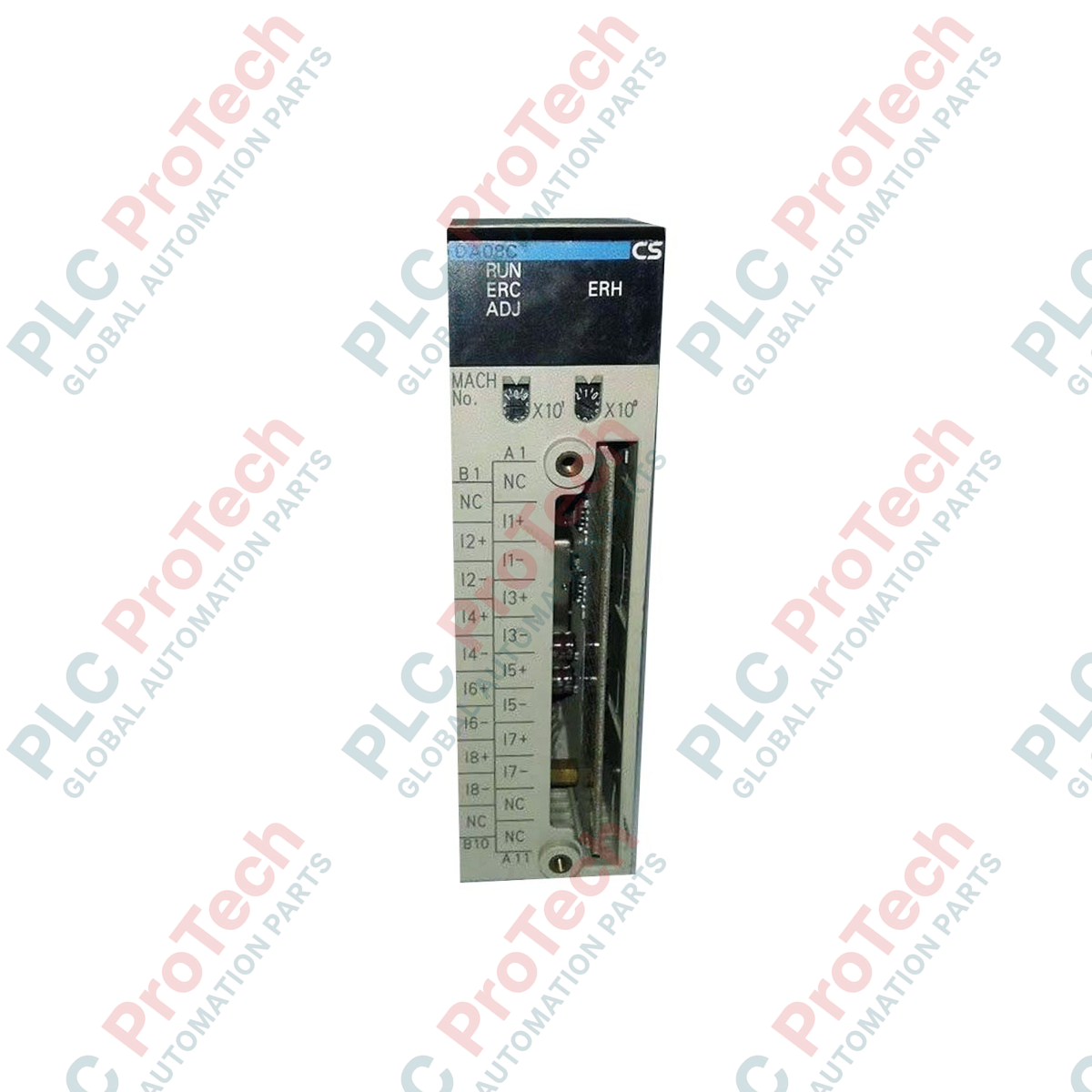
Processing of analog signals within the Omron CS1 PLC architecture is handled with high precision by the Omron CS1W-DA08C analog output module, which provides eight independent channels for process control loops. This high-density module mounts directly onto a CS1-series CPU rack or expansion rack, converting digital values within the PLC memory into standard voltage or current outputs. Each channel can be configured independently for various signal ranges, allowing the controller to interface simultaneously with different types of field actuators, control valves, and speed regulators. Built with industrial-grade isolation and a detachable terminal block, the CS1W-DA08C ensures reliable performance and minimized downtime during field servicing.
Features
-
Eight Independent Analog Outputs: Supports up to 8 field devices from a single module slot, optimizing rack space.
-
Flexible Signal Configuration: Output ranges can be set separately for each channel via the PLC's DM area settings.
-
Removable Terminal Block: Simplifies field wiring and allows rapid module replacement without disconnecting individual field wires.
-
Industrial Noise Immunity: High-grade isolation between the internal PLC bus and external field circuitry protects the control architecture.
-
Seamless System Integration: Fully compatible with Omron CS1-series backplanes and configurable via CX-Programmer software.
Applications
- Proportional control valve and damper positioning in combustion and HVAC systems.
- Speed reference signaling for variable frequency drives (VFDs) and servo controllers.
- Analog output re-transmission to chart recorders, panel indicators, or data loggers.
- Set-point distribution to secondary loop controllers in complex chemical or thermal processes.
Technical Specifications
| Parameter |
Specification |
| Manufacturer |
Omron |
| Model Number |
CS1W-DA08C |
| Module Type |
Analog Output Module |
| Number of Analog Outputs |
8 channels |
| Output Signal Ranges (Voltage) |
1 to 5 V, 0 to 10 V, 0 to 5 V, -10 to 10 V |
| Output Signal Ranges (Current) |
4 to 20 mA |
| Signal Selection Method |
Set separately for each output channel via PLC memory |
| External Connection |
Removable terminal block |
| Internal Current Consumption (5 VDC) |
0.13 A |
| External Current Consumption (24 VDC) |
0.25 A (listed as 25V in legacy reference data) |
| Operating Temperature |
0 to 55 degC |
| Country of Origin |
Japan |
| Shipping Weight (Calculated) |
1.5 kg |
| Package Dimensions (Calculated) |
150 mm x 135 mm x 50 mm |
Empirical Engineering Insights
Alternative Models & Compatibility
The CS1W-DA08C is standard for systems requiring high-density voltage/current outputs. It differs from the CS1W-DA08V in connection style; the "C" suffix denotes a terminal block interface rather than a high-density connector, simplifying direct wiring in standard control panels. When migrating legacy C500-series hardware to CS1, this module is the designated modern replacement for C500-DA001/DA005 units, though addressing structures in CX-Programmer must be updated to match the CS1 DM-area allocations.
Application Pitfalls & Engineering Notes
A common field failure point is the loss of the external 24 VDC power supply to the module. If external power drops below critical levels, the module will trigger an error, and all outputs will default to their de-energized states (typically 0V or 0mA, depending on safe-state configuration). PLC logic should always monitor the module’s health status bits and handle interlocks to prevent process surges or uncontrolled valve travel during a power loss event.
Commissioning & Wiring Tips
To ensure high signal integrity, use twisted-pair shielded cables for all analog runs and ground the shields at only one end (typically at the PLC panel ground bar). Ensure the rotary unit number switches on the front of the CS1W-DA08C are set correctly before powering up the rack; these switches define the starting address of the allocated DM words where individual channel ranges and conversion parameters are written.
Installation Guidelines
CRITICAL WARNING:
De-energize the entire PLC rack and turn off all external 24 VDC power supplies before installing, removing, or performing maintenance on the module. Hot-swapping the module can result in permanent hardware damage, CPU faulting, or unexpected actuator movement in the field.
1
Set the Unit Number rotary switch on the front panel of the module to a unique value matching your CX-Programmer I/O allocation.
2
Align the module's top and bottom guides with the target slot on the CS1 backplane and press the module firmly until it clicks into place.
3
Connect the pre-wired terminal block to the front of the module and tighten the retaining screws to secure the interface.
4
Apply 24 VDC external power to the designated terminals, power up the PLC rack, and download the configuration data to begin commissioning.