


Implementing 3-Switch XOR Ladder Logic with Internal Bit
Implement a 3-SPST switch XOR light circuit in LogixPro or RSLogix 500 using an internal relay bit. Includes truth tables, boolean equations, and verified.

The Omron NX-TS3202 Temperature Input Unit provides high-density, high-precision RTD monitoring for industrial automation systems operating on the Omron NX-series bus. This module interfaces directly with Pt100 three-wire resistance temperature detectors, offering precise multi-channel thermal feedback to Sysmac machine controllers or remote I/O couplers. Built for harsh factory environments, it features robust galvanic channel-to-channel isolation to prevent ground loops and protect upstream control electronics from high-voltage transients.
| Specification Parameter | Value / Details |
|---|---|
| Manufacturer | Omron |
| Model Number | NX-TS3202 |
| Input Channels | 4 points (Resistance thermometer) |
| Sensor Compatibility | Pt100 (three-wire) |
| Conversion Time | 10 ms per Unit |
| Resolution | 0.01 degC max. |
| I/O Refreshing Method | Free-Run refreshing |
| Input Detection Current | Approx. 0.25 mA |
| Conductor Resistance Influence | 0.06 degC/Ohm max. (up to 20 Ohm max.) |
| Isolation Method | Transformer (Power), Digital Isolator (Signal) [Inputs to NX Bus & between inputs] |
| Dielectric Strength | 510 VAC between isolated circuits for 1 minute (leakage current <= 5 mA) |
| Insulation Resistance | 20 MOhm minimum at 100 VDC between isolated circuits |
| NX Unit Power Consumption | 1.50 W max (on CPU Unit); 1.05 W max (on Coupler Unit) |
| Physical Dimensions | 24 (W) x 100 (H) x 71 (D) mm |
| Net Weight | 0.13 kg |
| Shipping Weight (Calculated) | 1.5 kg |
| Terminal Row | Terminal Connection Assignment (Pt100 3-Wire) |
|---|---|
| Terminal Block A | Inputs for Channel 0 & Channel 1 (A, B, B' wiring contacts + shield termination point) |
| Terminal Block B | Inputs for Channel 2 & Channel 3 (A, B, B' wiring contacts + shield termination point) |
The unit uses standard three-wire Pt100 RTDs. It should not be confused with the NX-TS3101 series, which is dedicated to thermocouple interfaces, or the NX-TS3201, which features a different channel configuration. When replacing older units, verify that Sysmac Studio has been updated to support the unit configuration to prevent hardware identification mismatches on the EtherCAT network coupler.
This module relies on precise physical excitation currents (approximately 0.25 mA). Cable lengths must be designed to minimize conductor resistance; resistance over 20 Ohms per wire will degrade measurement accuracy, adding up to 0.06 degC/Ohm of drift. To achieve the specified conversion accuracy, the module requires a continuous warm-up period of at least 30 minutes after power-up.
Always use high-quality shielded twisted-pair (STP) wiring for sensor lines. Terminate the shield at the ground terminal block on the NX-series unit or system ground bar to suppress high-frequency electrical noise from nearby variable frequency drives (VFDs). Do not route RTD sensor cables parallel to high-voltage power lines in the wire duct.
Shut off all power supplies connected to the NX-series bus CPU or communication coupler before installing, removing, or wiring the module. Failure to de-energize the assembly can cause permanent component damage to the unit’s internal logic circuits or disrupt field communications.
Mount the module by aligning the top hook of the unit with the DIN rail and pressing down firmly until you hear the sliding hook click into place.
Insert the pre-stripped three-wire Pt100 cables directly into the screwless clamp terminal block. Use a flat-blade screwdriver to release the tension clamp if removing wires.
Verify correct LED TS indicator behavior after system initialization. A solid green light indicates normal bus communication and functional sensor acquisition.
Global Express Shipping
Returns & Warranty

Manufacturer: Omron
Product No.: NX-TS3202
Country of origin:Japan
Product Type: Temperature Input Units
Payment: T/T, Western Union
Weight: 130g
Dimensions: 24 (W) x 100 (H) x 71 (D) mm
Shipping port: Xiamen
Warranty: 12 months
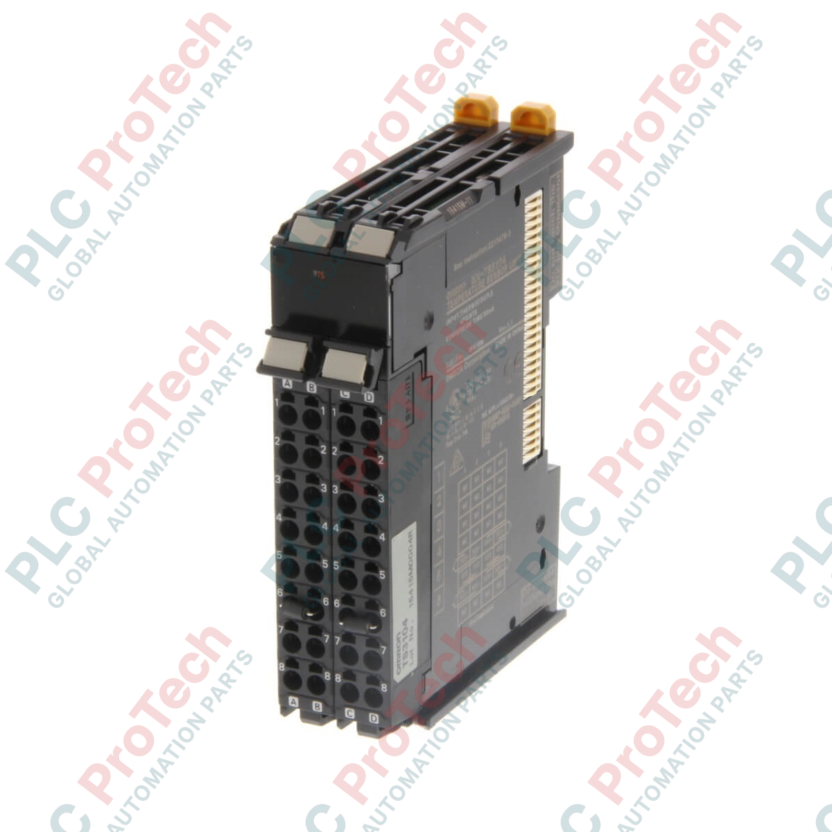
The Omron NX-TS3202 Temperature Input Unit provides high-density, high-precision RTD monitoring for industrial automation systems operating on the Omron NX-series bus. This module interfaces directly with Pt100 three-wire resistance temperature detectors, offering precise multi-channel thermal feedback to Sysmac machine controllers or remote I/O couplers. Built for harsh factory environments, it features robust galvanic channel-to-channel isolation to prevent ground loops and protect upstream control electronics from high-voltage transients.
| Specification Parameter | Value / Details |
|---|---|
| Manufacturer | Omron |
| Model Number | NX-TS3202 |
| Input Channels | 4 points (Resistance thermometer) |
| Sensor Compatibility | Pt100 (three-wire) |
| Conversion Time | 10 ms per Unit |
| Resolution | 0.01 degC max. |
| I/O Refreshing Method | Free-Run refreshing |
| Input Detection Current | Approx. 0.25 mA |
| Conductor Resistance Influence | 0.06 degC/Ohm max. (up to 20 Ohm max.) |
| Isolation Method | Transformer (Power), Digital Isolator (Signal) [Inputs to NX Bus & between inputs] |
| Dielectric Strength | 510 VAC between isolated circuits for 1 minute (leakage current <= 5 mA) |
| Insulation Resistance | 20 MOhm minimum at 100 VDC between isolated circuits |
| NX Unit Power Consumption | 1.50 W max (on CPU Unit); 1.05 W max (on Coupler Unit) |
| Physical Dimensions | 24 (W) x 100 (H) x 71 (D) mm |
| Net Weight | 0.13 kg |
| Shipping Weight (Calculated) | 1.5 kg |
| Terminal Row | Terminal Connection Assignment (Pt100 3-Wire) |
|---|---|
| Terminal Block A | Inputs for Channel 0 & Channel 1 (A, B, B' wiring contacts + shield termination point) |
| Terminal Block B | Inputs for Channel 2 & Channel 3 (A, B, B' wiring contacts + shield termination point) |
The unit uses standard three-wire Pt100 RTDs. It should not be confused with the NX-TS3101 series, which is dedicated to thermocouple interfaces, or the NX-TS3201, which features a different channel configuration. When replacing older units, verify that Sysmac Studio has been updated to support the unit configuration to prevent hardware identification mismatches on the EtherCAT network coupler.
This module relies on precise physical excitation currents (approximately 0.25 mA). Cable lengths must be designed to minimize conductor resistance; resistance over 20 Ohms per wire will degrade measurement accuracy, adding up to 0.06 degC/Ohm of drift. To achieve the specified conversion accuracy, the module requires a continuous warm-up period of at least 30 minutes after power-up.
Always use high-quality shielded twisted-pair (STP) wiring for sensor lines. Terminate the shield at the ground terminal block on the NX-series unit or system ground bar to suppress high-frequency electrical noise from nearby variable frequency drives (VFDs). Do not route RTD sensor cables parallel to high-voltage power lines in the wire duct.
Shut off all power supplies connected to the NX-series bus CPU or communication coupler before installing, removing, or wiring the module. Failure to de-energize the assembly can cause permanent component damage to the unit’s internal logic circuits or disrupt field communications.
Mount the module by aligning the top hook of the unit with the DIN rail and pressing down firmly until you hear the sliding hook click into place.
Insert the pre-stripped three-wire Pt100 cables directly into the screwless clamp terminal block. Use a flat-blade screwdriver to release the tension clamp if removing wires.
Verify correct LED TS indicator behavior after system initialization. A solid green light indicates normal bus communication and functional sensor acquisition.
Global Express Shipping
Returns & Warranty
Orders are processed and delivered Monday-Friday (excluding public holidays).
For full eligibility, restocking fees, and international return details, please view our official Refund & Return Policy .
| Country of origin |
Japan
|

Implement a 3-SPST switch XOR light circuit in LogixPro or RSLogix 500 using an internal relay bit. Includes truth tables, boolean equations, and verified.

Integrate Allen-Bradley CompactLogix, Caterpillar ATS, and generators into DeltaV DCS over Modbus RTU. Covers ProSoft MVI69-MCM, Miille DIN266 gateways.

ONS instruction fires but the OTE coil never latches in Studio 5000 because the one-shot is only true for one scan. Use OTL/OTU or seal-in logic instead.

Configure Allen-Bradley Kinetix 5500 servo drives on EtherNet/IP. Covers CIP Sync, IEEE 1588 V2 timing, Stratix selection, DLR topology, and HMI.

A moving-average filter is the sliding-window smoother most instrument engineers drop into DCS and PLC analog paths. Here is how the window works, how N and sample time set lag, and when a...

On Frame 5–9 gas turbines, GE Mark VI and Mark VIe run control as function-block application software. This article maps process, protection, and sequencing functions—and what Toolbox ST access...