Description
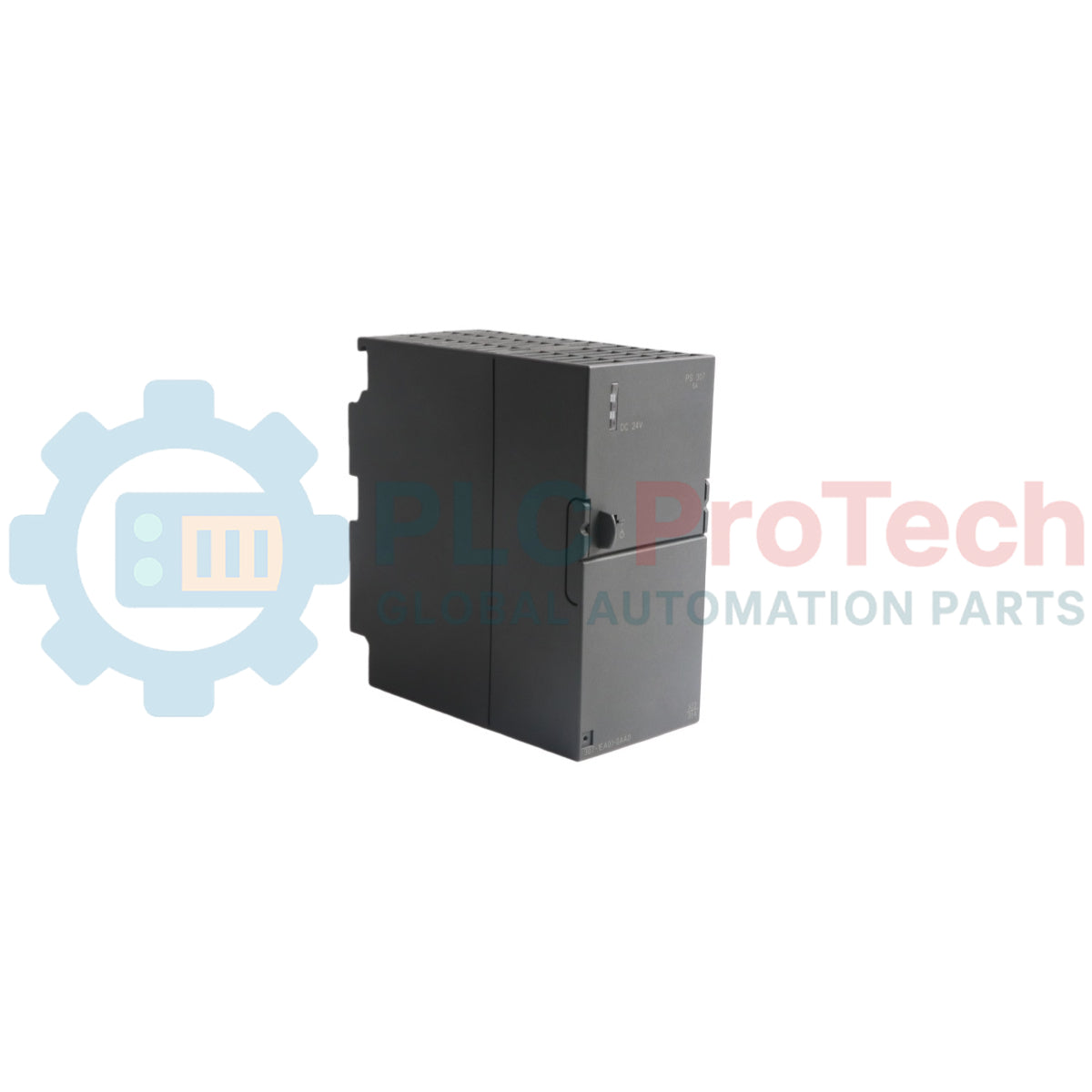
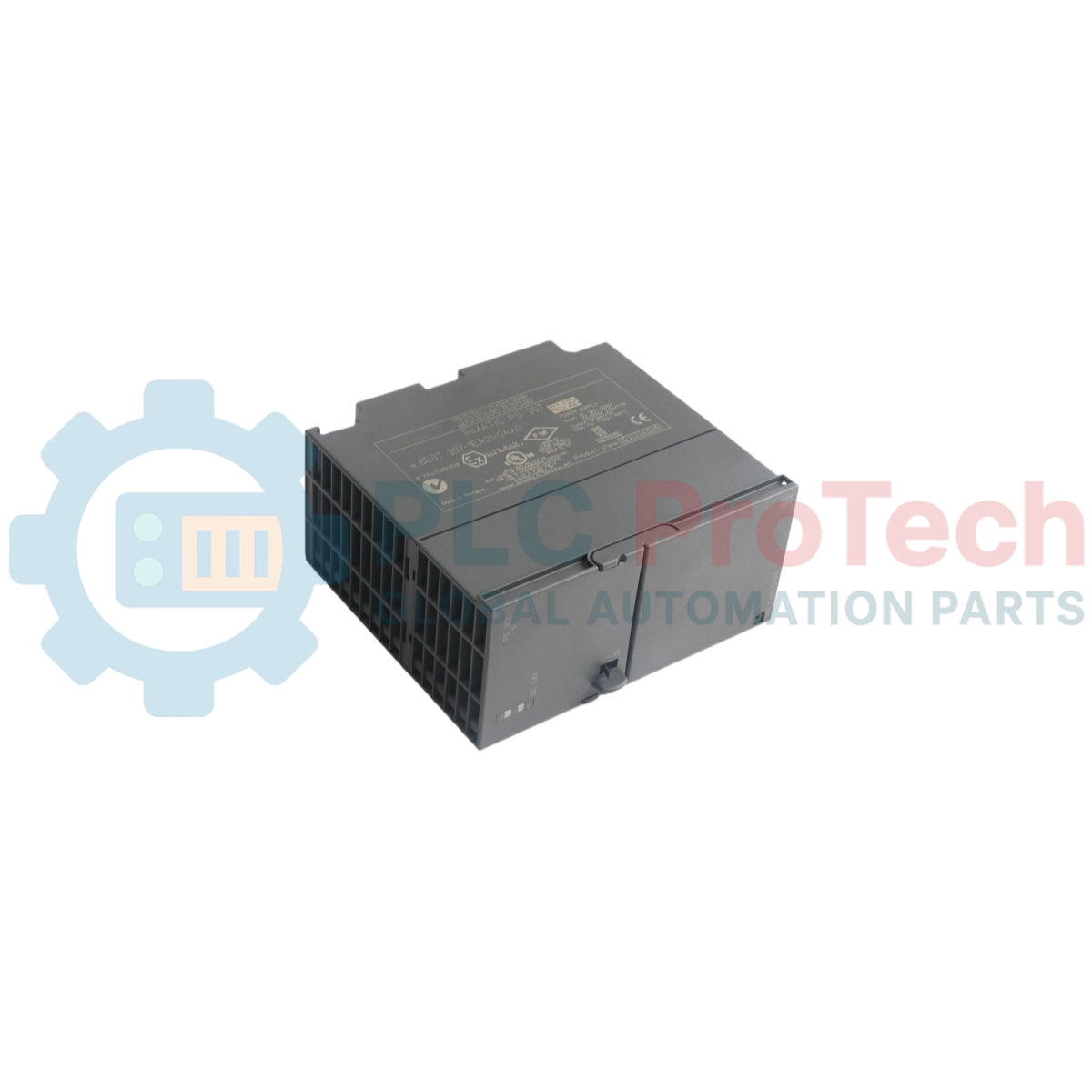
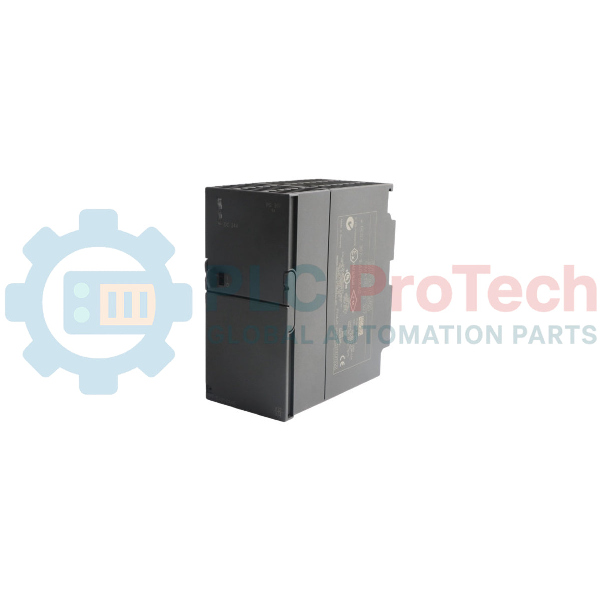
This is the Siemens 6ES7307-1EA01-0AA0, a stabilized PS 307 power supply module engineered specifically for the SIMATIC S7-300 PLC system. It reliably converts a standard 120/230V AC line voltage into a regulated 24V DC output, providing the essential power backbone for the entire S7-300 rack. With a robust output current capacity of 5 A, this module ensures stable operation for the CPU and multiple I/O modules, even in fully expanded configurations, preventing voltage dips that could lead to system faults.
Features
-
■Stabilized 24V DC output voltage
-
■5 A rated output current capacity
-
■Wide-range AC input for global compatibility
-
■Automatic input voltage range selection (120/230V AC)
-
■Designed for seamless integration into the SIMATIC S7-300 rack
-
■Provides electrical isolation to protect sensitive control electronics
Applications
-
■Manufacturing and Assembly Lines
-
■Process Control Systems
-
■Material Handling and Conveying
-
■Building Automation Systems
-
■Water and Wastewater Treatment Facilities
Technical Specifications
| Specification |
Value |
| Manufacturer |
Siemens |
| Model Number |
6ES7307-1EA01-0AA0 |
| Product Series |
SIMATIC S7-300 |
| Module Type |
PS 307 Power Supply |
| Input Voltage |
120 / 230 V AC |
| Output Voltage |
24 V DC |
| Output Current |
5 A |
| Product Status |
Active |
| Shipping Weight |
0.95 kg |
| Package Dimensions (Calculated) |
15 cm x 14 cm x 6 cm |
| Country of Origin |
Germany |
Installation Guidelines
CRITICAL WARNING: Hazardous voltages are present. Installation must be performed by qualified personnel only. Disconnect and lock out all power sources before installation or removal to prevent electric shock and equipment damage.
-
1
Verify that all power to the S7-300 rack is de-energized and locked out according to safety procedures.
-
2
Mount the module onto the SIMATIC S7-300 mounting rail, typically on the far left side of the rack assembly. Ensure it is securely seated.
-
3
Connect the 120/230V AC line, neutral, and protective earth (PE) conductors to the corresponding input terminals on the front of the module. Verify correct polarity and secure connections.
-
4
Slide the module to the right to engage its backplane connector with the adjacent CPU or interface module, establishing the 24V DC power link to the system bus.
-
5
After all modules are installed and wiring is double-checked, remove the lockout/tagout and restore power to the system. Verify the "24V DC" indicator LED on the front of the module is illuminated.