Description
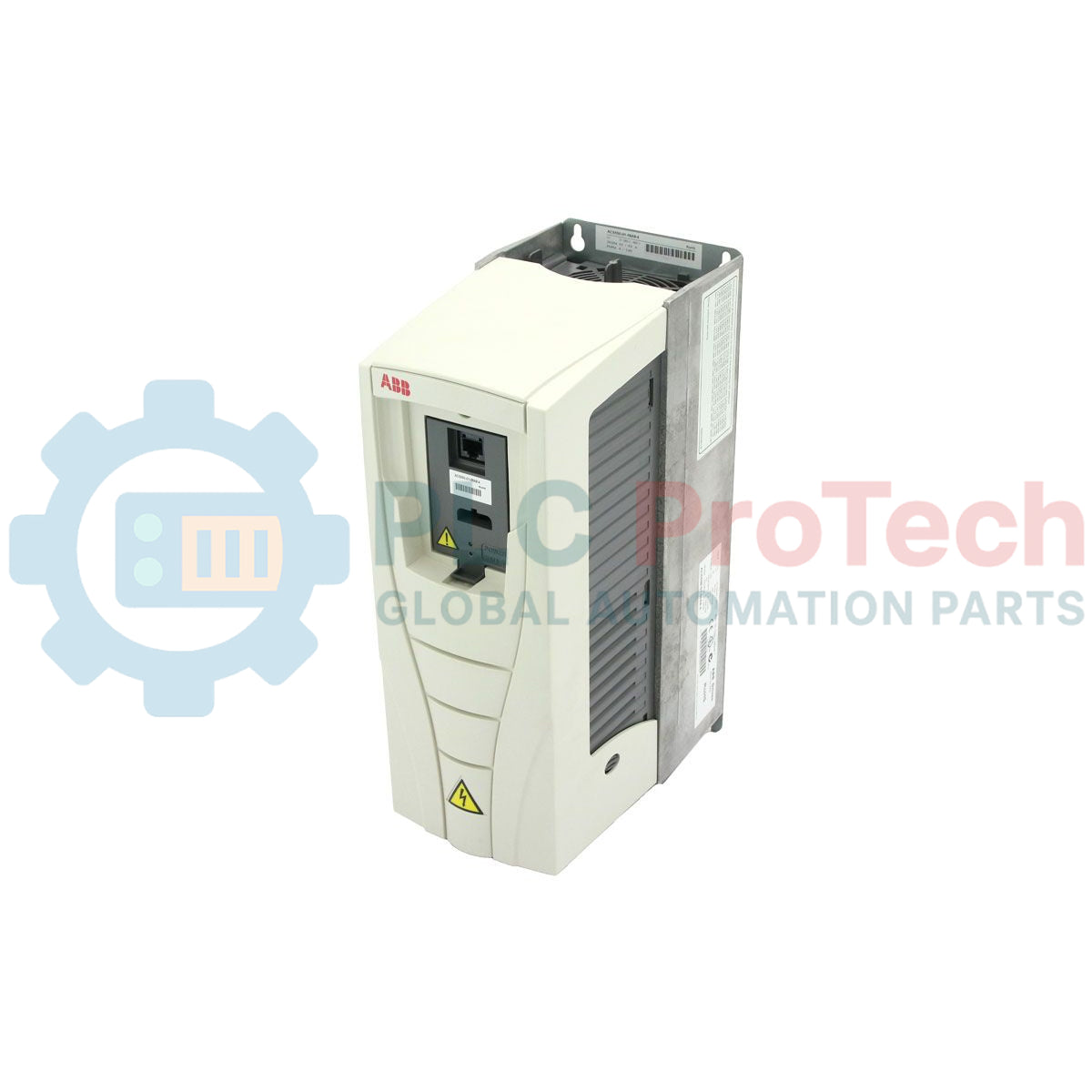
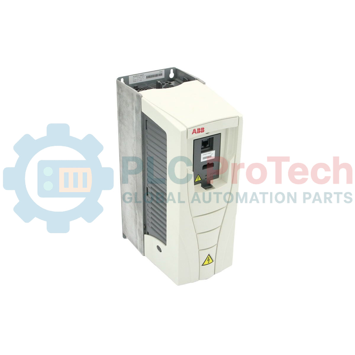
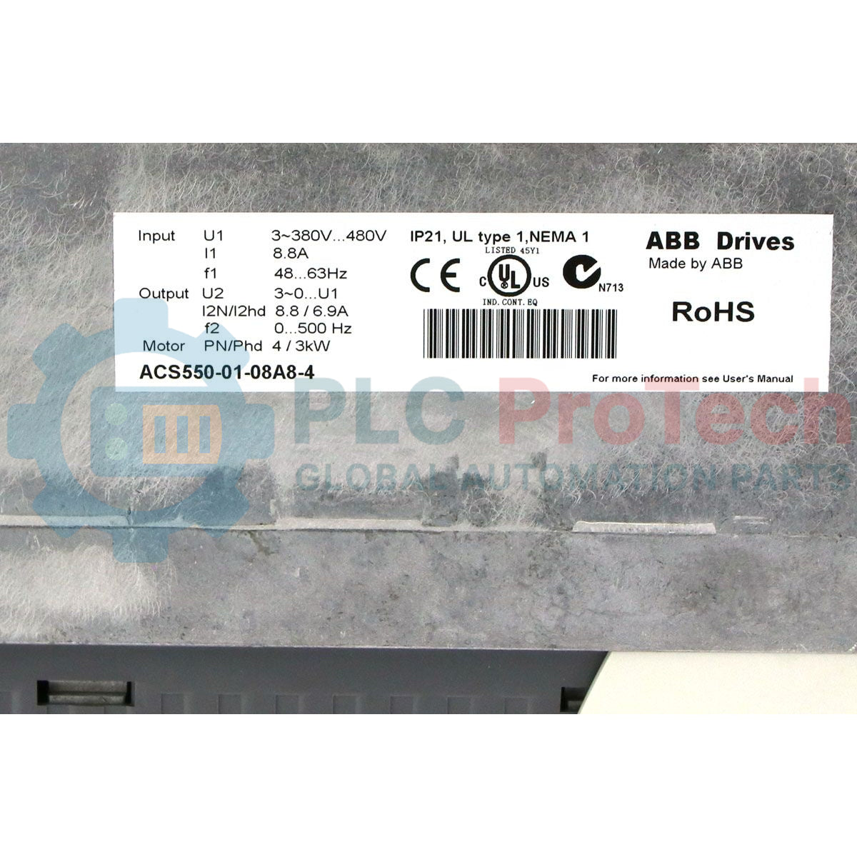
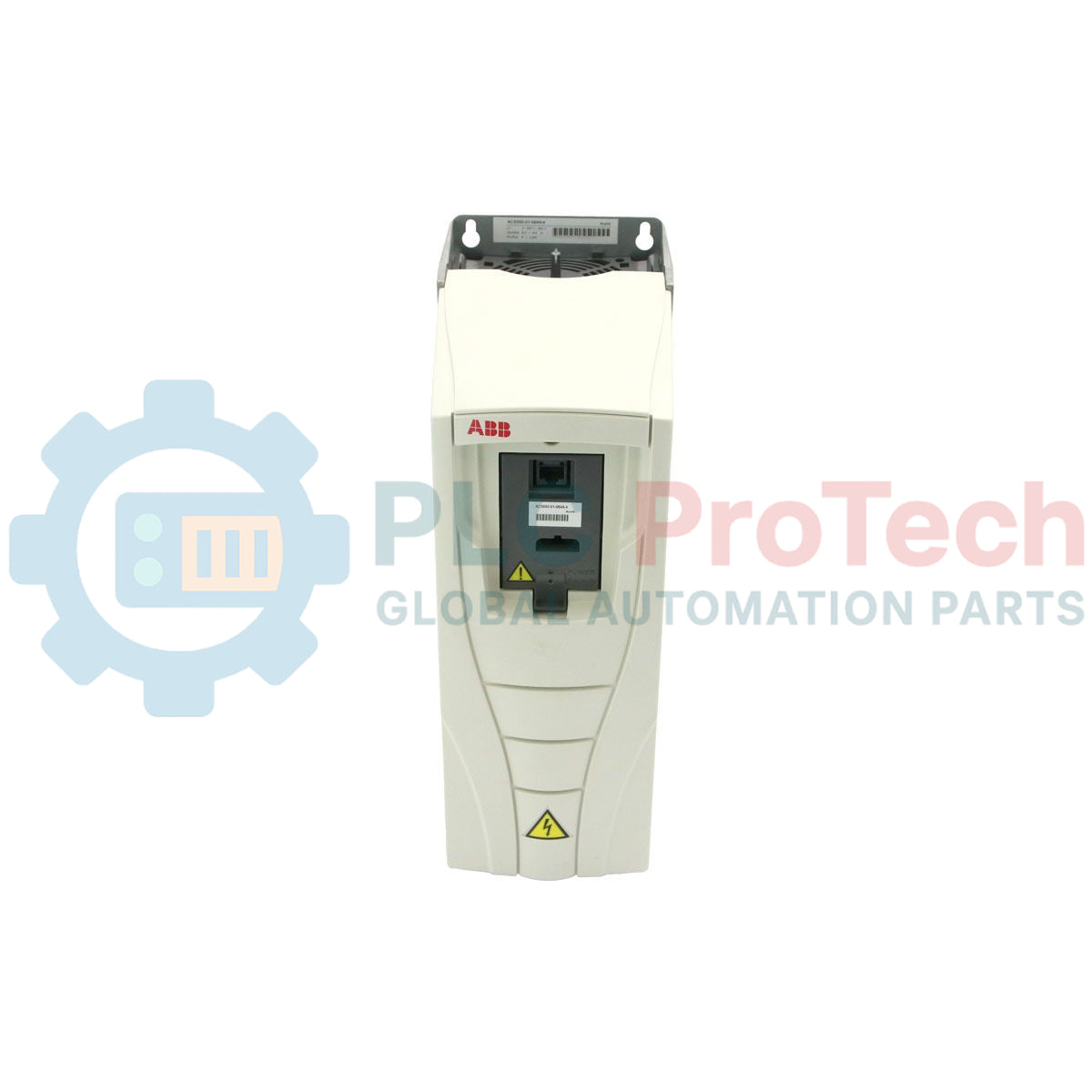
Engineered to deliver precise speed and torque control for three-phase induction motors, the ABB ACS550-01-08A8-4 variable frequency drive integrates seamlessly into low-voltage industrial power systems. This highly reliable motor controller supports an output power rating of 4 kW (5 HP) under normal duty conditions and operates across a standard supply voltage range of 380 to 480 V AC. As part of the established ACS550 series, this drive features an integrated swinging choke that significantly lowers harmonic distortion compared to standard line reactors, enhancing the operational lifespan of connected electrical infrastructure. The unit is housed in a robust IP21 protection enclosure, making it ideal for standard wall-mounted industrial installations requiring dependable thermal dissipation and compact spatial footprints.
Features
-
Patented Swinging Choke: Reduces line harmonics up to 25% at partial loads without the bulk of external line reactors.
-
Flexible Control Modes: Supports scalar (V/Hz) and sensorless vector control for adaptable torque profiles.
-
Integrated EMC Filter: Built-in RFI/EMC filter ensures compliance with European and domestic high-frequency interference standards.
-
Native Fieldbus Interface: Standard Modbus RTU interface on RS-485 terminals simplifies integration into distributed SCADA architectures.
-
FlashDrop Compatibility: Enables parameter uploading and drive programming in seconds without applying main power.
Applications
- Centrifugal pumps requiring energy-efficient flow control and quadratic torque profiles.
- Industrial supply and exhaust fans utilizing speed-regulated HVAC air distribution.
- Material handling conveyors demanding controlled acceleration and deceleration ramps to prevent mechanical stress.
- Mixers, agitators, and dosing systems requiring constant low-speed torque stability.
Technical Specifications Table
| Parameter |
Specification |
| Manufacturer |
ABB |
| Model Number |
ACS550-01-08A8-4 |
| Series |
ACS550 Standard Drive |
| Input Voltage Range |
380 to 480 V AC (+10% / -15%) |
| Number of Phases |
3-Phase Input / 3-Phase Output |
| Normal Duty Output Power |
4 kW (5 HP) |
| Normal Duty Output Current |
8.8 A |
| Heavy Duty Output Power |
3 kW (4 HP) |
| Heavy Duty Output Current |
6.9 A |
| Input Frequency Range |
48 to 63 Hz |
| Enclosure Rating |
IP21 (UL Type 1) |
| Control Connections |
2 Analog Inputs, 2 Analog Outputs, 6 Digital Inputs, 3 Relay Outputs |
| Communications |
Modbus RTU (Embedded) |
| Product Dimension (W x H x D) |
12.50 x 36.90 x 21.20 cm |
| Net Shipping Weight |
6.50 kg |
| Commodity Code |
85044095 |
Connections and Interfaces
| Terminal Designation |
Function / Assignment |
| U1, V1, W1 |
3-Phase AC Power Input Terminals |
| U2, V2, W2 |
3-Phase AC Variable Frequency Output to Motor |
| BRK+, BRK- |
Dynamic Braking Resistor External Connections |
| AI1 / AI2 |
Analog Inputs (Voltage 0...10V / Current 0/4...20mA) |
| AO1 / AO2 |
Analog Outputs (Programmable, standard 0/4...20mA) |
| DI1...DI6 |
Digital Inputs (Configurable, 12...24V DC PNP/NPN logic) |
| RO1, RO2, RO3 |
Relay Outputs (Form C, programmable, max 250V AC / 30V DC) |
Alternative Models & Compatibility
The ACS550-01-08A8-4 directly replaces legacy Frame R1 ACS400 drives with minimal mechanical adaptation. When retrofitting, note that digital I/O macros may default to "ABB Standard"; ensure your existing control wire maps match the programmed macro. For network upgrades, this VFD is fully compatible with optional fieldbus modules including the RPBA-01 (Profibus-DP), RCAN-08 (CANopen), and RETA-01 (EtherNet/IP / Modbus TCP).
Application Pitfalls & Engineering Notes
For high-elevation installations exceeding 1000 meters above sea level, the output current must be derated by 1% for every additional 100 meters. Additionally, when using motor cables longer than 100 meters (328 feet), parasitic capacitance to earth can cause false "F0016" (Earth Fault) trips. In these configurations, an external du/dt filter or output reactor must be installed to protect the drive's output IGBT bridge and prevent winding degradation on older motors.
Commissioning & Wiring Tips
To configure analog input signals, ensure the onboard DIP switches (located behind the Assistant Control Panel assembly on the control board) match the desired input signal type: Switch J1 controls AI1 (Voltage/Current) and Switch J2 controls AI2 (Voltage/Current). Ensure control wiring is run in separate conduits from high-power motor and input cables to prevent high-frequency noise coupling. Always ground the motor cable shield 360 degrees at both the VFD clamp and the motor terminal box.
Installation Guidelines
CRITICAL WARNING: ELECTRICAL HAZARD
Before beginning any installation, maintenance, or terminal wiring, disconnect all input power sources and lock out all disconnects. Wait a minimum of 5 minutes after de-energizing the drive to allow the internal DC bus capacitors to discharge fully. Verify zero voltage across terminals U1/V1/W1 and the DC bus terminals prior to handling internal components.
1
Mount the drive vertically on a flat, non-flammable surface, ensuring at least 200 mm of clearance above and below the cooling fan assembly for unimpeded vertical airflow.
2
Connect the input power conductors to terminals U1, V1, and W1, and the protective earth (PE) grounding conductor to the drive's primary chassis ground terminal.
3
Terminate the motor cables to U2, V2, and W2 using symmetrically shielded motor cables to minimize electromagnetic radiation and bearing currents.
4
Wire control, interlock, and emergency stop circuits to the I/O terminals, separating them by at least 200 mm from the high-voltage power lines.