Descrição
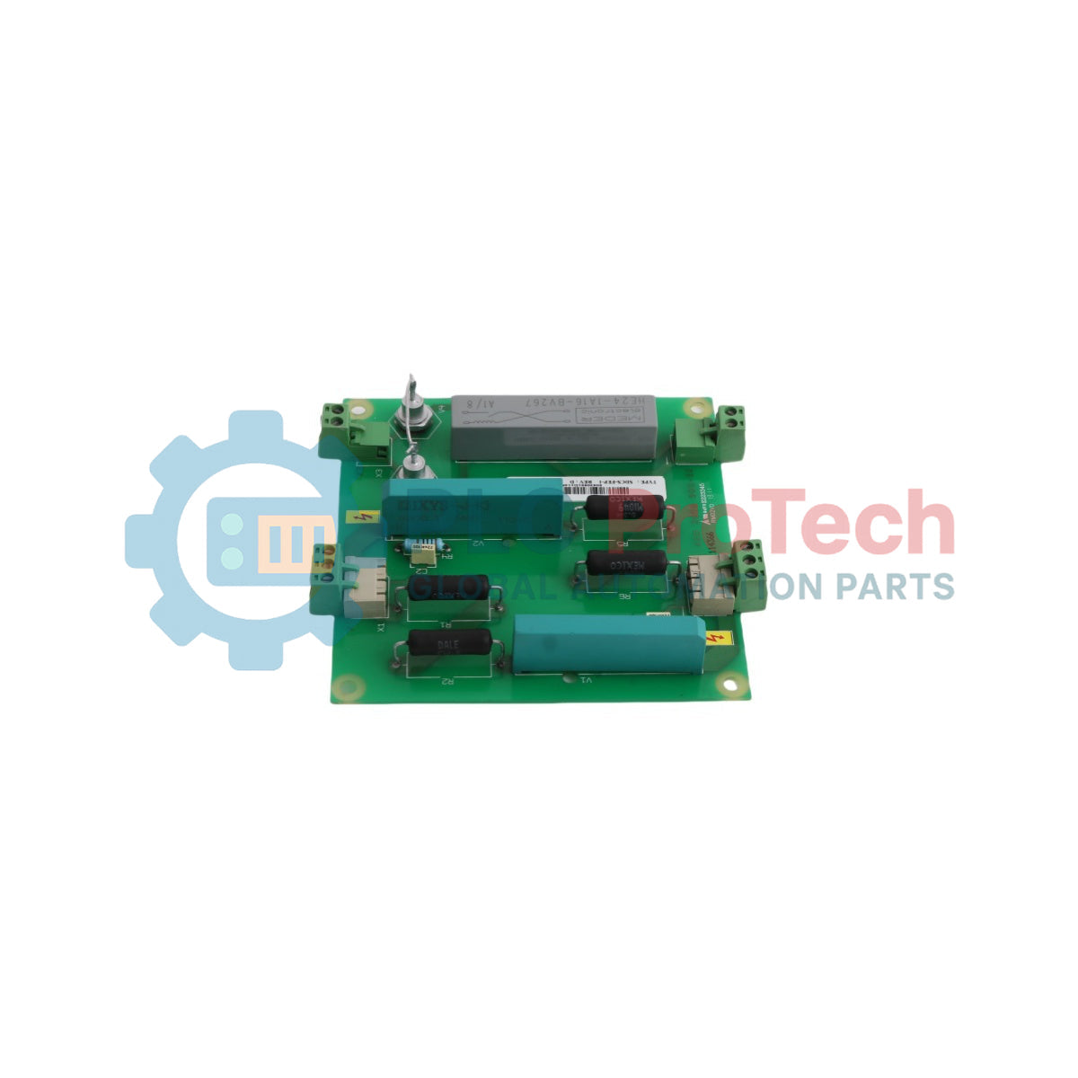
O ABB SDCS-FEP-1 é um conjunto de interface dedicado à proteção contra sobretensão e sobrecorrente, projetado para conversores de potência com tiristores e redes industriais de distribuição CC com múltiplos acionamentos. Funcionando como uma unidade de proteção de campo de alta integridade dentro da matriz do conversor, este componente eletrônico atua como um buffer defensivo entre os enrolamentos externos do campo do motor e a eletrônica de controle interna.
O SDCS-FEP-1 limita ativamente surtos de alta tensão, realimentação transitória do campo e picos de tensão indutiva comuns em grandes circuitos de controle de máquinas CC. O módulo de hardware, registrado sob o número de peça 3BSE006309R0001, utiliza varistores industriais especializados e caminhos dedicados de desacoplamento para isolar a infraestrutura delicada de processamento de falhas no circuito de campo, prevenindo a propagação de falhas através de barramentos internos de energia compartilhados.
Características
-
Supressão de Tensão Transitória: Suprime surtos de linha de alta energia causados por descarga indutiva do campo ou aberturas súbitas do disjuntor primário.
-
Separação Galvânica do Circuito: Protege os controladores principais do acionamento mantendo falhas elétricas do lado do campo localizadas, afastadas das placas de microprocessadores.
-
Baixa Impedância de Inserção: Integra-se perfeitamente em circuitos padrão de excitação de motores sem afetar o monitoramento de corrente ou a estabilidade da regulação do campo.
Aplicações
- Supressão de surtos no enrolamento do campo do motor CC e circuitos de segurança contra sobretensão dentro de painéis conversores industriais.
- Instalações industriais pesadas de acionamento, como configurações de fornos de cimento, controles de grandes guindastes e laminadores de metais.
Especificações Técnicas
| Parâmetro |
Especificação |
| Fabricante |
ABB |
| Designação do Modelo |
SDCS-FEP-1 |
| ID do Produto / Número do Pedido |
3BSE006309R0001 |
| Agrupamento Funcional |
Unidade de Proteção de Campo |
| Status do Tipo de Peça |
Original / Novo |
| País de Origem |
Tailândia (TH) |
| Peso para Envio (Calculado) |
0,148 kg |
| Dimensões da Embalagem (Calculadas) |
185 mm x 120 mm x 45 mm |
Insights Empíricos de Engenharia
Modelos Alternativos e Compatibilidade
A unidade SDCS-FEP-1 substitui diretamente o componente legado catalogado como 3BSE007486R0001. Para sistemas que requerem interfaces atualizadas do lado do campo, esta placa também é funcionalmente substituída pelo grupo de peças 3ADT220090R0021. Sempre verifique as configurações físicas do envelope dos terminais e as restrições de espaçamento de trilhas ao realizar atualizações de troca ao vivo em estruturas de conversores legados.
Armadilhas de Aplicação e Notas de Engenharia
Quando os loops de excitação de campo descarregam durante sequências de desligamento de emergência, a energia absorvida pelas placas de supressão protetora pode gerar picos térmicos rápidos. Certifique-se de que a fiação de controle não isolada que passa próxima não entre em contato com os caminhos de supressão de alta energia. Se ocorrer uma falha persistente de aterramento de campo, esses elementos de fixação podem sofrer falha estrutural, resultando em curtos-circuitos de baixa impedância entre os trilhos de alimentação.
Diretrizes de Instalação
AVISO CRÍTICO: ALTA TENSÃO E REQUISITOS DE DESENERGIZAÇÃO
Desconecte completamente, isole e bloqueie todas as vias principais de corrente alternada trifásica a montante e as linhas auxiliares secundárias de corrente contínua que alimentam a baia do conversor de acionamento. Circuitos indutivos de campo geram potenciais indutivos residuais altos após a desenergização do sistema. Espere pelo menos 15 minutos para a dissipação completa da energia e use um dispositivo de teste certificado para confirmar o status absoluto sem energia antes de tentar interagir com os terminais.
1
Prenda uma pulseira antiestática verificada e conecte seu aterramento a uma parte de aço exposta da estrutura do sistema.
2
Identifique e desacople os caminhos de fiação dos terminais de campo e puxe os cabos de feedback de diagnóstico de baixa tensão dos canais da placa.
3
Assente a placa nos clipes espaçadores do painel, fixe todos os parafusos de fixação estrutural para construir uma referência limpa de loop de terra e retermine as conexões de fiação de campo.