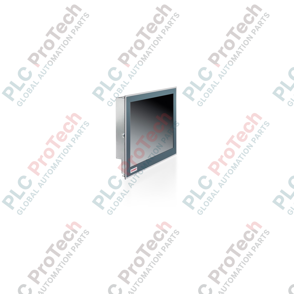
Description
Fulfilling the demand for space-saving control interfaces, the Beckhoff CP6601-0021-0020 built-in Panel PC combines an industrial-grade touch display with a reliable ARM Cortex-A8 processor to execute precise control and visualization tasks directly at the machine level. This hardware integration functions as an optimized control node, utilizing its 1 GHz processing core and Windows Embedded Compact 7 environment to run TwinCAT-based PLC automation projects with low power consumption. The mechanical design incorporates a robust aluminum front frame with a sheet-steel rear cover, engineered specifically for flush installation within control cabinets or console enclosures.
Features
-
Efficient ARM Processing: Equipped with an ARM Cortex-A8 processor running at 1 GHz for deterministic control and real-time visualization.
-
High-Speed Memory Architecture: Features 1 GB DDR3 RAM paired with onboard NOVRAM for secure system variables and volatile parameter buffering.
-
Dual Network Interfaces: Built-in independent ports for standard 10/100BASE-T Ethernet and high-speed EtherCAT fieldbus networking.
-
Integrated MicroSD Storage: Includes a dedicated slot supporting microSD cards up to 16 GB for system software, boot projects, and user configurations.
-
Hardware-Level UPS: Outfitted with an integrated 1-second capacitive uninterruptible power supply (UPS) to safely back up persistent data to NOVRAM during sudden power loss.
-
Industrial Environmental Protection: IP65 front-panel rating ensures resistance to dust, moisture, and water spray under operating conditions.
Applications
- Machine-level Human-Machine Interface (HMI) for specialized manufacturing cells.
- Compact controller and visualization nodes within packaging, material handling, and assembly systems.
- Decentralized data acquisition and protocol gateway stations linking field devices to higher-level networks.
- Sub-system controls requiring direct EtherCAT master capabilities inside space-restricted control panels.
Technical Specifications
| Specification Parameter |
Value / Rating |
| Manufacturer |
Beckhoff |
| Model Number |
CP6601-0021-0020 |
| Processor |
ARM Cortex-A8, 1 GHz |
| Motherboard |
3.5-inch compact motherboard |
| System Memory |
1 GB DDR3 RAM |
| Persistent Memory |
128 kByte NOVRAM |
| Storage Slot |
1 x microSD slot (512 MB standard, expandable up to 16 GB) |
| Operating System |
Windows Embedded Compact 7 (English) |
| TwinCAT Performance Level |
TwinCAT 2: PLC level 30 / TwinCAT 3: PLC level 30 |
| Supply Voltage |
24 V DC (-15% / +20%) |
| UPS Architecture |
Integrated 1-second capacitive UPS |
| Display and Touch |
5.7-inch (640 x 480) with single-finger analog resistive touch screen |
| Housing Material |
Aluminum front frame with sheet-steel rear protective cover |
| Operating Temperature |
0 to 55 degC |
| Protection Rating |
Front side IP65, rear side IP20 |
| Country of Origin |
Germany |
| Shipping Weight (Calculated) |
5.0 kg |
Connections and Interfaces
| Port / Interface Label |
Connector Type |
Functional Assignment |
| LAN (X101) |
RJ45 |
1 x 10/100BASE-T Ethernet port for network integration |
| EtherCAT (X102) |
RJ45 |
Real-time on-board EtherCAT master interface |
| USB 1 & USB 2 |
USB Typ-A |
2 x USB 2.0 host interfaces for external input and updates |
| COM1 (X105) |
D-sub 9-pin |
1 x RS232 serial interface for peripheral device communication |
| Power Input |
3-pin terminal block |
24 V DC main power connection and UPS ground reference |
Empirical Engineering Insights
Alternative Models & Compatibility
The CP6601-0021-0020 serves as an optimized, embedded replacement for older ARM9-based control panels. When migrating from legacy displays running Windows CE 6 to Windows Embedded Compact 7 on this device, ensure your TwinCAT boot project target platform is updated to ARMv7. The compiled binaries for older ARM9 architectures must be rebuilt in TwinCAT 2/3 to prevent runtime instruction-set mismatch faults during startup.
Application Pitfalls & Engineering Notes
The integrated 1-second capacitive UPS is designed exclusively to back up critical variables in the 128 kByte NOVRAM during an unexpected power disruption. This UPS does not support runtime buffering of the entire Windows system image; it is highly critical that cyclic file-writing operations directly to the microSD card are structured carefully. Excessive continuous writes can lead to premature wear of the microSD sectors, which can corrupt the operating system partition during system restarts.
Commissioning & Wiring Tips
To protect the resistive touchscreen from static-induced register shifts, ensure the front bezel makes solid electrical contact with the cabinet metalwork, and that the cabinet is tied to a low-impedance ground. Use shielded CAT5e or CAT6 cabling for both the RJ45 Ethernet and EtherCAT connections. Route communication cables separately from high-current motor cables and variable frequency drives to suppress electromagnetic interference (EMI).
Installation Guidelines
CRITICAL WARNING: Prior to attempting any mechanical installation or wiring of this device, isolate all 24 V DC power sources. Verify that all auxiliary components and adjacent equipment are completely de-energized. Do not mount the unit in environments exceeding the rated operating limit of 55 degC, and maintain sufficient clearance behind the rear steel cover to allow passive convection cooling.
1
Prepare Panel Cutout: Prepare the installation cutout matching the standard dimensions for the 5.7-inch housing. Smooth and deburr all sharp sheet metal edges to prevent damage to the integrated front seal gasket.
2
Mount with Clamping Levers: Insert the Panel PC into the cutout from the front. Secure the unit using the built-in pull-out mechanical clamping levers accessible from the rear side. Tighten uniform pressure to compress the front gasket for IP65 dust and moisture protection.
3
Attach Ground and Control Wiring: Connect the functional grounding wire from the panel frame directly to the central grounding rail. Plug the 24 V DC power supply lines into the provided 3-pin terminal block matching designated polarities.
4
Establish Network Links: Insert the dedicated EtherCAT line into port X102 and the standard TCP/IP networking line into port X101. Run the system and observe the diagnostic LEDs to confirm proper physical link activity.