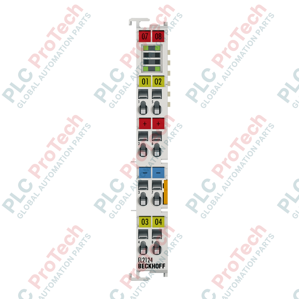
Description
Integrating directly into high-speed automation architectures, the Beckhoff EL2124 provides fast, precise digital control over four independent 5 V DC channels. Engineered for rapid switching dynamics, this EtherCAT Terminal utilizes a CMOS push-pull output design capable of actively sourcing and sinking up to 20 mA per channel. Ideal for interfacing with low-voltage logic levels, optocouplers, and high-frequency digital receivers, the module features sub-microsecond propagation delays to ensure real-time response times within critical control loops.
Key Features
-
High-Speed Signal Processing: Sub-microsecond switching times (typically under 1 us for both turn-on and turn-off phases) designed for time-critical motion and gating control.
-
Four CMOS Push-Pull Outputs: Supports active high and active low signaling, providing a robust 5 V DC logic driving capacity.
-
Integrated Short-Circuit Protection: Ruggedized engineering design protects the module against wiring faults and overcurrent conditions on all output channels.
-
Comprehensive Galvanic Isolation: 500 V electrical isolation between the E-bus and the field potential safeguards upstream backplane communications.
Industrial Applications
- High-frequency optocoupler and pulse receiver interfacing
- Low-voltage logic level shifting and micro-controller integration
- High-speed material sorting, triggering, and gating systems
- Testbench automation and electronic hardware-in-the-loop (HIL) simulations
Technical Specifications
| Specification Parameter |
Technical Value |
| Manufacturer |
Beckhoff |
| Model Series |
EtherCAT Terminal (EL Series) |
| Number of Outputs |
4 channels |
| Nominal Output Voltage |
5 V DC |
| Output Driver Type |
CMOS push-pull (source/sink) |
| Maximum Output Current |
+/- 20 mA per channel (short-circuit proof) |
| Switching Propagation Delay |
TON < 1 us, TOFF < 1 us |
| Current Consumption (E-bus) |
Typically 130 mA |
| Current Consumption (Power Contacts) |
Typically 12 mA + load |
| Electrical Isolation |
500 V (E-bus to field potential) |
| Load Type Compatibility |
Ohmic, lamp load |
| Operating Temperature |
0 degC to +55 degC |
| Storage Temperature |
-25 degC to +85 degC |
| Relative Humidity |
95%, non-condensing |
| Connection Technology |
2-wire or 3-wire direct connection |
| Connection Cross-Section (Solid/Stranded) |
0.08 mm2 to 2.5 mm2 (AWG 28 to 14) |
| Connection Cross-Section (Ferrule) |
0.14 mm2 to 1.5 mm2 (AWG 26 to 16) |
| Ingress Protection Rating |
IP20 (conforms to EN 60529) |
| Ex Marking / Hazardous Location |
II 3 G Ex nA IIC T4 Gc |
| Country of Origin |
Germany |
| Physical Dimensions |
Width: 12 mm
Height: 100 mm
Depth: 68 mm |
| Shipping Weight (Calculated) |
0.15 kg |
| Package Dimensions (Calculated) |
150 mm x 120 mm x 40 mm |
Empirical Engineering Insights
Alternative Models & Compatibility
The terminal integrates directly into standard TwinCAT 2.x and 3.x system structures. While utilizing the same physical footprint as typical 24 V DC terminals, the unit requires dedicated 5 V DC logic-side distribution. Ensure that any downstream configurations do not inadvertently route field voltages above the rated 5 V threshold to this module.
Application Pitfalls & Engineering Notes
Because this module utilizes standard CMOS push-pull outputs, it actively drives the signaling line both high and low. Avoid connecting multiple output channels in parallel to boost current driving capabilities, as minor switching delays between channels can induce transient short circuits. Additionally, verify the E-bus power supply margins of your coupler segment; a single terminal consumes 130 mA typical E-bus current.
Commissioning & Wiring Tips
For signal transmission distances exceeding 3 meters, shielded twisted-pair cabling is strongly recommended to minimize environmental electromagnetic interference. Ground the cable shield securely at the control panel boundary plate to isolate high-speed CMOS switching channels from structural floor noise.
Installation Guidelines
CRITICAL WARNING:
De-energize the entire control system and disconnect all field power contacts before installing, servicing, or extracting any EtherCAT terminal. Failure to do so can result in electrical arcing, destruction of sensitive CMOS drivers, or transmission faults across the adjacent E-bus.
1
Mount the terminal onto a standard 35 mm DIN rail (conforming to EN 60715) and verify that the locking mechanism engages securely with the rail profile.
2
Align adjacent terminals using the side-by-side double slot and key connection, checking that the internal gold E-bus contact pins connect smoothly without mechanical force.
3
Strip wiring insulation to exactly 8-9 mm. Actuate the internal spring clamp using a flat-head screwdriver, insert the solid or ferruled conductor, and release the tool to clamp.
4
Power up the segment and initiate terminal detection and routing parameters using the TwinCAT System Manager software tree.