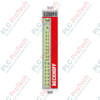
Description
Executing high-precision current regulation directly within the EtherCAT I/O architecture, the Beckhoff EL2535-0002 serves as a dedicated 2-channel pulse width current terminal designed for 24 V DC systems. By utilizing advanced push-pull output technology, this terminal adjusts the output current value from zero up to the maximum load limit via current-controlled pulse width modulation of the supply voltage. Grounded in professional-grade design, the module features robust galvanic isolation from the internal E-bus to protect control-level electronics from field disturbances, while integrated diagnostic LEDs provide clear, real-time feedback for local status and wiring fault detection.
Features
- Dual-channel architecture supporting independent PWM current-controlled outputs.
- Push-pull output stage configuration optimized for inductive and resistive loads.
- Full electrical isolation between the E-bus and field potential up to 500 V.
- Onboard diagnostic LEDs indicating signal state, load faults, and wiring conditions.
- Comprehensive protective circuitry preventing damage from overloads and short-circuits.
Applications
- Proportional valve control in hydraulic and pneumatic industrial machinery.
- Speed and torque modulation for low-power fractional horsepower DC motors.
- Thermoelectric cooler (Peltier element) current control in precision temperature chambers.
- Modulated power supply for industrial heating resistors and filament loads.
Technical Specifications
| Parameter |
Specification Value |
| Manufacturer |
Beckhoff |
| Model Number |
EL2535-0002 |
| Number of Channels |
2 |
| Nominal Voltage |
24 V DC (-15 percent / +20 percent) |
| Connection Technology |
PWM output, push-pull outputs |
| PWM Clock Frequency |
30 kHz (default) |
| Duty Cycle Range |
0 to 100 percent (current-controlled) |
| Resolution |
10 bit (internal PWM duty cycle) |
| E-Bus Current Consumption |
Typical 110 mA |
| Electrical Isolation |
500 V (E-bus / field potential) |
| Control Value Format |
16-bit signed integer |
| Weight |
0.05 kg |
| Shipping Weight (Calculated) |
0.15 kg |
| Package Dimensions (Calculated) |
120 mm x 80 mm x 25 mm |
Connections and Interfaces
| Terminal Contact Point |
Signal Assignment |
Functional Details |
| 1 |
Output 1 + |
Positive PWM Output Channel 1 |
| 5 |
Output 1 - |
Negative PWM Output Channel 1 |
| 2 |
Output 2 + |
Positive PWM Output Channel 2 |
| 6 |
Output 2 - |
Negative PWM Output Channel 2 |
| 3 |
+24 V DC |
Field Power Feed (Positive Potential) |
| 7 |
0 V |
Field Power Feed (Ground Potential) |
| 4 |
Shield |
Functional Earthing / Electromagnetic Shield |
| 8 |
Shield |
Functional Earthing / Electromagnetic Shield |
Empirical Engineering Insights
Alternative Models & Compatibility
The EL2535-0002 must be configured via TwinCAT System Manager using the correct XML Device Description (ESI) corresponding to the module's hardware revision. Ensure that the terminal's firmware matches the minimum requirements of your TwinCAT deployment to utilize all 16-bit register mapping functions seamlessly.
Application Pitfalls & Engineering Notes
When switching highly inductive loads, such as large proportional valves, high back-EMF spikes can trigger the internal overcurrent or thermal shutdown mechanisms of the push-pull stages. To prevent nuisance tripping, engineers should verify that the internal clamping diode's energy dissipation capacity is not exceeded, or install external fast-recovery freewheeling diodes directly across the load terminals if duty cycles remain high at maximum current limits.
Commissioning & Wiring Tips
Due to the 30 kHz default switching frequency of the PWM outputs, the lines running to the load can act as active noise transmitters. It is highly recommended to run shielded, twisted-pair cabling for both output channels. Terminate the cable shields directly to contacts 4 or 8 on the terminal, and ensure a low-impedance ground connection is maintained on the DIN rail via a copper busbar or grounding terminal.
Installation Guidelines
CRITICAL WARNING: Prior to mounting, inserting, or removing any terminal block from the EtherCAT segment assembly, completely de-energize both the 24 V DC field power bus and the main E-bus power supplies. Failure to fully isolate all power sources can result in permanent optical or physical damage to the internal E-bus communication contacts.
1
Align the terminal with the DIN rail (TS35) and slide it firmly into place until the locking mechanism clicks securely.
2
Push the adjacent terminal blocks together to ensure the side-mounted E-bus contacts establish continuous and reliable low-resistance connections.
3
Using a standard flat-head screwdriver, insert the field wiring conductors into the push-in connection points according to the designated pinout configuration.
4
Verify correct grounding of the DIN rail to achieve optimal electromagnetic compatibility (EMC) and signal stability.