Description
Decentralized power routing and active channel management in harsh industrial environments are directly executed by the Beckhoff EP9214-0023 EtherCAT Box. This specialized module enables the energy-efficient switching of connected field-level EtherCAT devices by distributing control voltage (Us) and peripheral power (Up) across multiple distinct channels. Equipped with high-capacity 7/8-inch power connections for high-current loops and protective electronic fusing, it is engineered to serve as a reliable, space-saving power distribution hub in high-density automated topologies.
Features
- Four independent, electronic-overcurrent-protected 4-pin M8 outputs.
- Supports up to 4 A current load handling for both Us (control) and Up (peripheral) circuits per port.
- Decentralized, energy-efficient control via direct EtherCAT-driven switching commands.
- Heavy-duty 7/8-inch power connectors (5-pin) enabling robust feed and downstream daisy-chaining.
- Integrated potential-free signaling contact utilizing a standard M8 interface for external state verification.
- Dual-port M8 shielded EtherCAT bus connection supporting linear topologies.
- Robust, fully encapsulated PA6 polyamide housing built for direct-to-machine mount.
Applications
-
Automotive Assembly Lines: Distributed sensor/actuator power zoning and tool-change segment isolation.
-
Conveyor and Material Handling: Local power routing and safety-related standby switching of zone controllers.
-
Packaging and Food Processing: Direct machine-frame mounting in washdown zones without requiring secondary enclosures.
-
Robotics Applications: Modular power management systems where weight-optimized distributed components are required.
Technical Specifications
| Specification Parameter |
Technical Value |
| Manufacturer |
Beckhoff Automation |
| Model Number |
EP9214-0023 |
| Product Series |
EtherCAT Box (EP92xx series) |
| Nominal Supply Voltage |
24 V DC (-15% / +20%) |
| Bus Interface Connection |
2 x M8 socket, shielded, screw type |
| Power Outputs |
4 x M8 socket (4-pin), switchable |
| Max. Output Current |
4 A per M8 socket for both Us and Up |
| Power Feed Interface |
1 x 7/8-inch plug, 5-pin |
| Power Downstream Interface |
1 x 7/8-inch socket, 5-pin |
| Signaling Contact |
Potential-free make contact, M8 connector |
| Electrical Isolation |
500 V |
| Housing Material |
Polyamide (PA6) |
| Protection Rating |
IP65 / IP66 / IP67 (conforms to EN 60529) |
| Operating Temperature Range |
-25 to +60 degC |
| Storage Temperature Range |
-40 to +85 degC |
| Dimensions (W x H x D) |
60 mm x 126 mm x 26.5 mm |
| Weight (Net) |
Approx. 440 g |
| Shipping Weight (Calculated) |
2.0 kg |
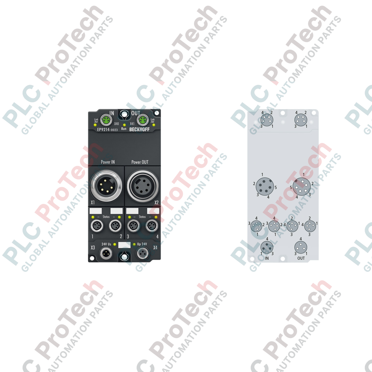
Connections and Interfaces
| Interface Type |
Pin / Terminal Number |
Function Assignment |
| 7/8-inch Power Connector |
Pin 1 |
GND_s (Ground for Control Voltage) |
| Pin 2 |
GND_p (Ground for Peripheral Voltage) |
| Pin 3 |
FE (Functional Earth) |
| Pin 4 |
Us (Control Voltage Feed, 24 V DC) |
| Pin 5 |
Up (Peripheral Voltage Feed, 24 V DC) |
| M8 Output Connectors (Channels 1 - 4) |
Pin 1 |
Us (Switched Control Voltage Out, 24 V DC, 4 A max) |
| Pin 2 |
Up (Switched Peripheral Voltage Out, 24 V DC, 4 A max) |
| Pin 3 |
GND_s (Control Ground Reference) |
| Pin 4 |
GND_p (Peripheral Ground Reference) |
Empirical Engineering Insights
Alternative Models & Compatibility
The EP9214-0023 differs from baseline non-switchable modules (such as the EP9214-0001) because it allows active PLC-driven shutdown of individual channels. When upgrading older lines, make sure that your PLC hardware configuration and GSDML/ESI files are updated in TwinCAT to allow for control mapping of the switching process image. Attempting to use a standard non-switchable driver mapping will prevent the outputs from turning on by default.
Application Pitfalls & Engineering Notes
When looping heavy downstream loads through multiple modules, calculate cumulative current across the 7/8-inch trunk line. The primary power feed connector has an absolute rating threshold that must not be exceeded. If total downstream current exceeds 16 A, you must split the feed topologies using separate feed points. Dropping voltages below 20.4 V DC (the -15% threshold) will cause downstream modules to report low-voltage faults and drop out of the EtherCAT ring.
Commissioning & Wiring Tips
Ensure that all unused M8 interfaces and 7/8-inch ports are sealed with standard, properly torqued IP67 protective caps. Operating the module with exposed pins voids the IP65/66/67 ratings and can lead to moisture ingress, which may damage the internal electronics. Additionally, keep the EtherCAT communication cables physically separated from motor or variable frequency drive power cables to avoid electromagnetic interference on the M8 network segments.
Installation Guidelines
CRITICAL SAFETY WARNING
Disconnect all control and system power feeds before mounting or wiring the module. High-current loops through 7/8-inch connectors present severe arc-flash risks. Verify that all auxiliary capacitor circuits have fully discharged before beginning work.
1
Mount the module flat to a machine-frame or mounting plate using the dual integrated fixing holes (3.5 mm holes for M3, or 4.5 mm holes for M4 fasteners).
2
Connect the functional earth (FE) to a ground potential using a short, low-resistance connection.
3
Securely connect the shielded M8 EtherCAT communication cables to the IN and OUT ports.
4
Connect the 7/8-inch main power feed cable to the inlet plug and torque the locking ring hand-tight to secure the IP-rated seal.