Description
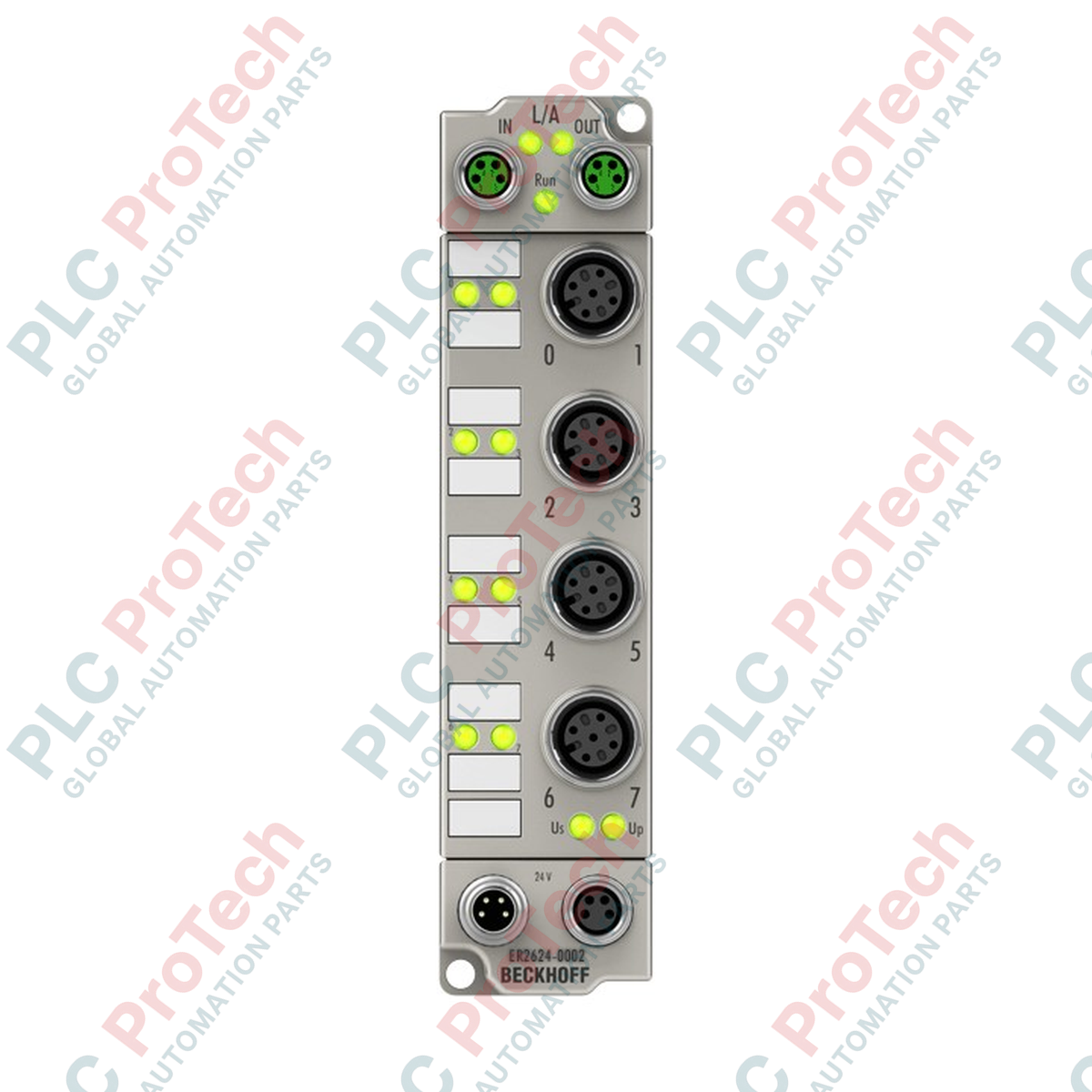
Functioning as a ruggedized distributed I/O solution, the Beckhoff ER2624-0002 industrial Ethernet module coordinates digital signal relaying directly in harsh field environments. Encased in a robust zinc die-cast housing, this IP67-rated EtherCAT Box provides four potential-free relay make contacts (normally open) designed to switch electromechanical loads up to 2 A DC or 0.5 A AC. By implementing direct fieldbus control without an electrical control cabinet, this module shortens cable runs, minimizes signal degradation, and optimizes system layout in decentralised automation topologies.
Features
-
Potential-Free Switching: Offers complete electrical isolation of 500 V between the control electronics and the load circuits.
-
Optimized Relay Outputs: Four independent make (NO) contacts capable of switching ohmic, inductive, and lamp loads.
-
Rugged Die-Cast Enclosure: Heavy-duty zinc housing provides superior mechanical resistance and high-grade electromagnetic shielding.
-
High-Durability Design: Engineered for extreme service life, achieving up to 100,000,000 mechanical operating cycles.
-
Direct Field Connection: Integrated dual M8 shielded screw-type connectors for the EtherCAT bus interface alongside standard M12 output interfaces.
Applications
- Decentralized control of low-voltage solenoids, contactors, and pneumatic valves.
- Wet processing areas, machine tools, and manufacturing lines requiring IP65/66/67 protection ratings.
- Test benches and automated assembly systems utilizing distributed switching structures.
- On-machine indicator lighting and audible alarm signaling.
Technical Specifications
| Parameter |
Specification |
| Manufacturer |
Beckhoff Automation |
| Model / Part Number |
ER2624-0002 |
| Fieldbus Protocol |
EtherCAT |
| Number of Outputs |
4 x make contacts (potential-free) |
| Rated Load Voltage |
25 V AC / 30 V DC |
| Ohmic Switching Current |
0.5 A AC / 2 A DC |
| Minimum Permitted Load |
10 microamps at 10 mV DC |
| Bus Interface |
2 x M8 socket, shielded, screw type |
| Output Connections |
M12 x 1, 5-pin, a-coded |
| Nominal Output Voltage |
24 V DC (-15% / +20%) |
| Current Consumption (from Us) |
120 mA |
| Operating Cycles (Mechanical) |
1 x 10^8 minimum |
| Operating Cycles (Electrical) |
2 x 10^5 minimum (at 1 A / 30 V DC) |
| Electrical Isolation |
500 V |
| Protection Rating |
IP65 / IP66 / IP67 (conforms to EN 60529) |
| Operating / Storage Temperature |
-25 to +60 degC / -40 to +85 degC |
| Vibration / Shock Resistance |
Conforms to EN 60068-2-6 / EN 60068-2-27 |
| EMC Immunity / Emission |
Conforms to EN 61000-6-2 / EN 61000-6-4 |
| Net Weight |
265 g |
| Shipping Weight (Calculated) |
2.0 kg |
| Approvals |
CE, UL |
Connections and Interfaces
| Interface Location |
Connector Type |
Pin Assignment / Signal |
| EtherCAT Input/Output |
2 x M8 socket, 4-pin, shielded |
Tx+, Rx+, Tx-, Rx- (standard EtherCAT transmission lines) |
| Output Channels (1 to 4) |
4 x M12 female, 5-pin, a-coded |
Pin 1 & Pin 2: Relay Contact; Pin 5: Functional Earth (FE) |
| Control Voltage Feed |
1 x M8 male, 4-pin |
Feed: Us (24 V DC system/sensor power), Up (peripheral/load power) |
| Downstream Power Link |
1 x M8 female, 4-pin |
Daisy-chain distribution of Us and Up voltages to next EtherCAT Box |
Empirical Engineering Insights
Alternative Models & Compatibility
The ER2624-0002 features a zinc die-cast housing designed to offer superior mechanical resistance and optimal shielding compared to its plastic-clad equivalent, the EP2624-0002. Both models share identical electronic components and pin assignments, allowing direct drop-in replacement within the TwinCAT System Manager software environment without requiring changes to the existing XML device description files.
Application Pitfalls & Engineering Notes
When switching inductive loads (such as DC contactors, solenoid valves, or brake coils), users must integrate external protective circuits (e.g., recovery diodes for DC loads or RC snubbers for AC loads) directly parallel to the load. Failing to suppress counter-electromotive force (back-EMF) transient spikes will cause contact arcing, drastically reducing the electrical service life of the internal miniature relays below the rated 200,000 cycles.
Commissioning & Wiring Tips
Ensure that both the Us (system and sensor power) and Up (peripheral voltage) lines are correctly stabilized. Even though the relays are potential-free, the internal logic requires a continuous 120 mA draw from the Us bus. For systems running long daisy-chained power lines, check for voltage drops; any dip below 20.4 V DC (24 V DC -15%) will trigger communication disruptions and cause erratic relay coil actuation.
Installation Guidelines
CRITICAL WARNING: De-energize all primary, peripheral, and load power supplies prior to physical installation, connector insertion, or configuration changes. Contact with high-voltage lines can cause severe electrical shock, equipment damage, or system-wide communication failure.
1
Position the module on a flat, grounded mounting plate or machine frame using the integrated mounting flanges. Secure with two M4 screws tightened to the specified torque limit.
2
Ensure direct metallic contact between the mounting plate and the module body to establish proper Functional Earth (FE) grounding paths.
3
Connect the incoming EtherCAT bus cable to the top-side M8 input socket, and route the output line to the subsequent box if using a daisy-chain topology. Tighten the collar to ensure IP67 sealing.
4
Plug the M12 actuator cables into the appropriate output ports (Channels 1 through 4), ensuring proper alignment of the a-coded keyway.
5
Verify that all unused M8 and M12 ports are sealed with approved protective caps to preserve IP67 fluid ingress protection ratings.