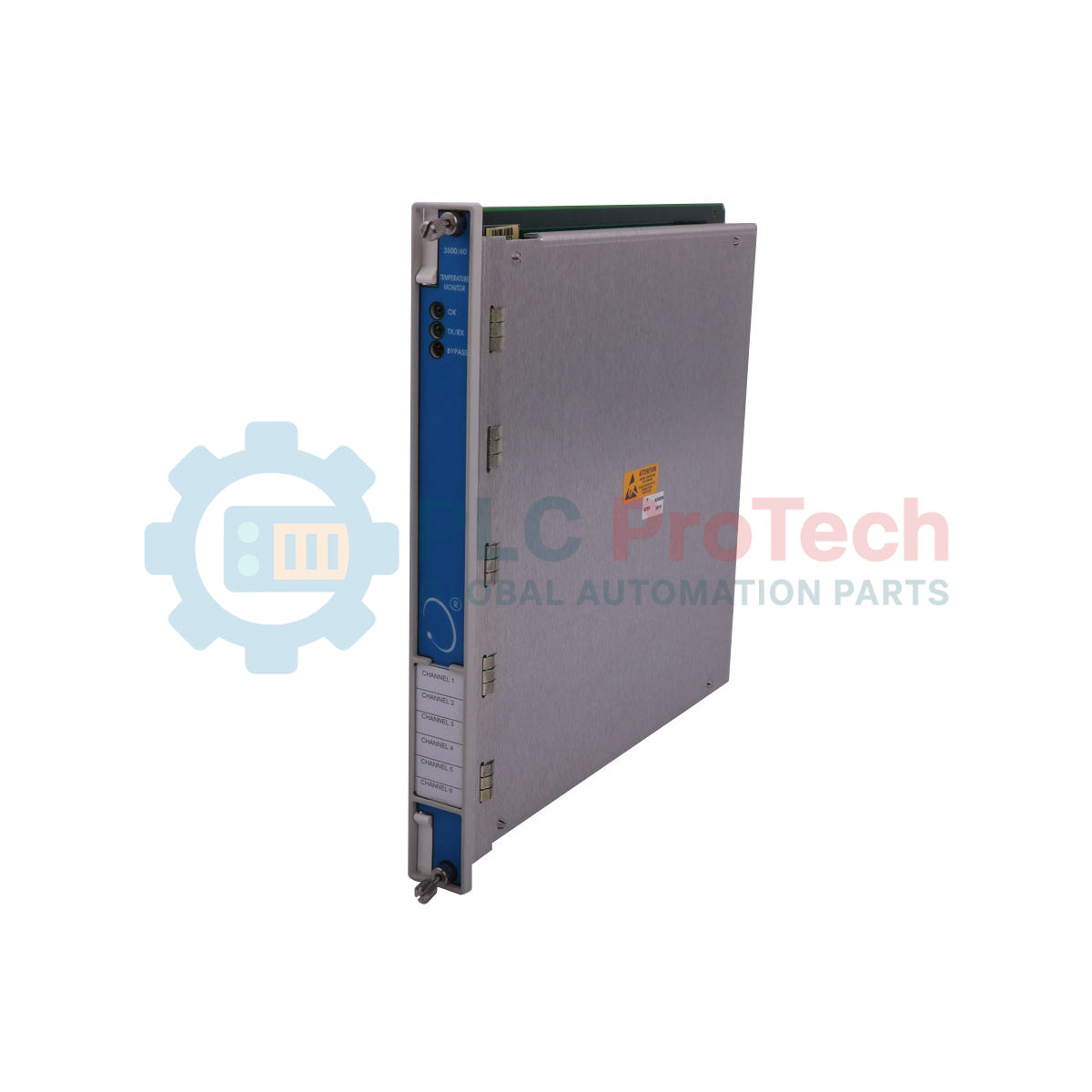
Description
Processing and continuous monitoring of temperature inputs within critical machinery protection systems is executed by the Bently Nevada 3500/60-01-00, a dedicated 3500 Series module configuration. This specialized module processes signals from both Resistance Temperature Detectors (RTDs) and Thermocouples (TC) to provide continuous, high-accuracy temperature tracking. Designed without recorder outputs, the 3500/60-01-00 utilizes an RTD/TC Non-Isolated I/O Module with Internal Terminations to maximize channel density and simplify wiring architectures directly within the monitor rack. It operates with a nominal power consumption of 7 watts, ensuring minimal thermal load inside the enclosure while delivering steady performance for machinery protection.
Features
-
Dual Sensor Compatibility: Dynamically processes inputs from both RTD and Thermocouple sensors on a single module frame.
-
Internal Terminations: Integrated wiring terminals reduce cabinet space requirements and simplify field installations.
-
High-Accuracy Monitoring: Delivers precise temperature verification for machinery components without the need for external signal conditioning.
-
Integration Integrity: Communicates directly with the 3500 System's backplane for high-speed alarm and trip generation.
-
Compact Form Factor: Fits into standard 3500 rack slots, supporting high-density machinery protection layouts.
Applications
- Steam, gas, and hydro turbine bearing temperature monitoring.
- Large industrial motor and generator winding protection.
- Compressor and high-pressure pump casing thermal monitoring.
- Gearbox and bearing oil sump temperature supervision.
Technical Specifications
| Manufacturer |
Bently Nevada |
| Model Number |
3500/60-01-00 |
| Series |
3500 Series Machinery Protection System |
| I/O Module Type |
01 - RTD/TC Non-isolated I/O Module |
| Termination Type |
Internal Terminations |
| Power Consumption |
7 Watts (Nominal) |
| Agency Approval Option |
00 - None |
| Recorder Outputs |
None |
| Country of Origin |
United States (USA) |
| Shipping Weight |
2.0 kg |
Alternative Models & Compatibility
The 3500/60-01-00 configuration utilizes a non-isolated I/O interface. If your site electrical design requires isolation to protect against high common-mode voltages or severe field noise, consider the 3500/60-02-00 variant, which integrates isolated I/O modules. Ensure that any replacement of the I/O module is matched by a corresponding configuration update within the 3500 Rack Configuration Software to prevent system configuration faults (slot mismatch errors).
Application Pitfalls & Engineering Notes
Because this module utilizes non-isolated I/O (Option 01), it shares a common ground across channels. It is critical that the RTD or thermocouple sensor tips installed on the machinery are electrically isolated from the machine frame. If a sensor tip becomes grounded to the machine frame, ground loops and common-mode voltages will degrade temperature readings, cause erratic measurements, or trigger false alarms. Always verify sensor insulation resistance during routine maintenance cycles.
Commissioning & Wiring Tips
When wiring to the internal termination block, use shielded, twisted-pair cables for all temperature sensor runs. Connect the shield drain wire only at the designated terminal on the 3500/60 I/O module. Do not connect the shield at the sensor junction box, as this will establish a ground loop. Keep signal wiring physically separated from high-voltage AC power lines to avoid electromagnetic interference on sensitive thermocouple readings.
Installation Guidelines
CRITICAL WARNING
De-energize the 3500 rack and all connected field circuitry before installing or removing modules. Live-plugging under load, especially on field I/O connections, poses a risk of electrical damage to the module circuitry and may cause unexpected tripping of connected machinery protection loops.
1
Ensure the 3500 rack power supplies are switched off and safety lockouts are active.
2
Align the main monitor module with the front slot guide rails and push firmly until the connector seats fully into the backplane. Secure the front panel screws.
3
Install the non-isolated I/O module (internal terminations) into the corresponding rear slot of the rack and secure the fastening screws.
4
Wire the RTD or Thermocouple sensors to the terminal strip following the designated pinout diagrams, ensuring shield wires are correctly terminated at the rack end.
5
Power up the rack and upload the correct software configuration using the 3500 Rack Configuration utility. Verify there are no system fault LEDs lit.