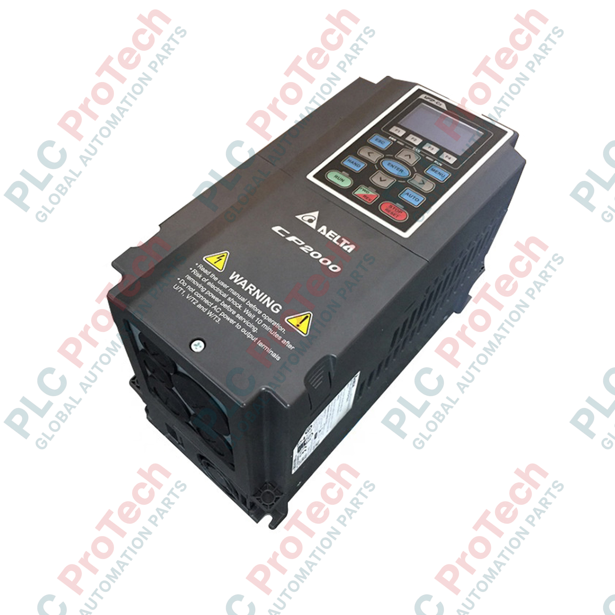
Description
Integrating advanced sensorless vector control with dedicated flow-control algorithms, the Delta Electronics VFD550CP43S-21 operates as a highly efficient variable frequency drive engineered for heavy-duty fan and pump operations. As part of the prestigious CP2000 Series, this unit is designed to optimize energy consumption in variable torque applications, delivering precise speed control under fluctuating load conditions. The drive features an integrated 10k-step PLC, allowing for localized control logic without the need for an external controller, making it a robust solution for modern HVAC, wastewater treatment, and industrial ventilation architectures.
Features
-
Intelligent Multi-Pump Control: Built-in modes for cyclic pump control, fixed-amount pump control, and PID feedback optimization.
-
Dual Communication Protocols: Integrated BACnet and Modbus RS-485 interfaces for seamless building automation and industrial SCADA integration.
-
Enhanced Fire Mode: Bypasses non-critical protective trips during emergencies to keep exhaust fans operating continuously.
-
Conformal Coating: PCB protection complies with IEC 60721-3-3 Class 3C3 for high humidity, dust, and corrosive gas environments.
-
Energy-Saving V/f Curve: Dynamically adjusts output voltage relative to load variations to minimize electrical consumption.
Applications
- Municipal water distribution networks and wastewater aeration systems.
- Commercial HVAC cooling towers, chillers, and secondary hot water circulators.
- Industrial cleanroom air handling units (AHUs) and smoke extraction systems.
- Constant pressure booster pump systems for high-rise commercial structures.
Technical Specifications
| Parameter |
Value |
| Manufacturer |
Delta Electronics |
| Model Number |
VFD550CP43S-21 |
| Product Series |
CP2000 Series |
| Applicable Motor Power |
75 HP (56.25 kW) |
| Rated Output Current |
105 Amps |
| Input Voltage / Phase |
460V AC, 3-Phase (Range: 380V to 480V) |
| Control Method |
V/f control, Sensorless Vector Control (SVC) |
| Enclosure Rating |
IP20 / NEMA 1 |
| Installation Type |
Wall Mount (Frame E1 size) |
| Operating Temperature |
-10 degC to 50 degC (De-rate above 40 degC) |
| Physical Dimensions (W x H x D) |
11.02 in x 24.19 in x 10.04 in |
| Net Weight |
40.0 kg (88.18 lbs) |
| Shipping Weight (Calculated) |
42.0 kg (92.59 lbs) |
Connections and Interfaces
| Terminal Block / Port |
Functional Assignment |
| R/L1, S/L2, T/L3 |
3-Phase AC Main Power Input Terminals |
| U/T1, V/T2, W/T3 |
Output Terminals to 3-Phase Induction Motor |
| MI1 to MI8 |
Multi-Function Digital Inputs (Sink/Source selectable via switch) |
| AVI / ACI |
Analog Voltage Input (0-10V) / Analog Current Input (4-20mA) for PID reference |
| RA, RB, RC |
Multi-Function Relay Output (SPDT contact, 250VAC/30VDC, 5A) |
| RJ-45 Port |
Dual-port communication interface for RS-485 Modbus and BACnet MS/TP |
Empirical Engineering Insights
Alternative Models & Compatibility
The VFD550CP43S-21 serves as a direct drop-in replacement for older Delta VFD-F series models of equivalent ratings. Note that when migrating from the VFD-F series, control wire terminal positions are physically relocated, and parameter maps must be reconfigured as the CP2000 series uses a highly modernized, descriptive parameter structure. Hardware frame dimensions are identical to Frame E1 layouts, ensuring no panel restructuring is required.
Application Pitfalls & Engineering Notes
When utilizing the integrated Multi-Pump control mode to sequence up to 8 secondary booster pumps, a critical engineering mistake is neglecting the interlock delay times. Ensure that parameter 12-04 (Pump Interlock Time) is configured to a minimum of 1.5 seconds to prevent contactor racing and transient back-EMF feedback into the output IGBT bridge of the drive. Additionally, in ambient operating spaces exceeding 40 degC, reduce the carrier frequency setting (Parameter 00-17) to 4 kHz to avoid thermal derating shutdowns.
Commissioning & Wiring Tips
To mitigate electromagnetic interference (EMI) on the analog inputs (AVI/ACI), ensure the shield drain wire of the 4-20mA pressure transducer feedback loop is grounded ONLY at the drive-end common terminal (ACM). Never ground the shield at both ends, as this generates a ground loop, introducing artificial offset values to the internal PID controller. For RS-485 networks, a 120-ohm termination resistor switch (located next to the RJ-45 port) must be engaged on the physically last drive on the network segment.
Installation Guidelines
CRITICAL WARNING: Hazardous high voltage remains present on the internal DC-bus capacitors for up to 10 minutes after main AC power is disconnected. Measure the DC-bus voltage at the (+1) and (-) terminals with an isolated digital multimeter to confirm it has decayed below 36V DC before commencing terminal rewiring or mounting adjustments.
1
Mount the drive vertically to an unpainted, flat metal sub-panel using M8 bolts. Ensure a minimum clearances of 150mm (5.9 inches) above and below the drive chassis for optimal convection cooling.
2
Execute all AC input power wiring (R/L1, S/L2, T/L3) and motor output wiring (U/T1, V/T2, W/T3) using shielded symmetrical motor cable with cross-sections rated for at least 75 degC copper conductor.
3
Ensure the ground terminal (PE) is connected directly to the facility system earth ground plate. Resistance to ground must not exceed 0.1 ohms to satisfy EN 61800-3 EMC standards.