Description
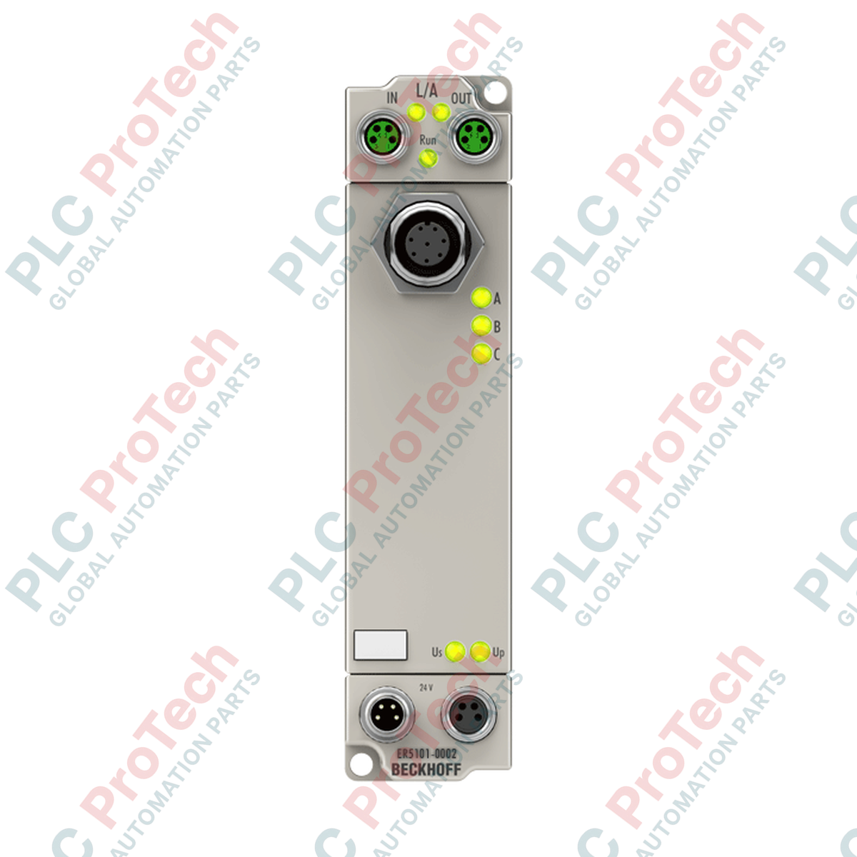
Engineered for precise motion control feedback in harsh industrial zones, the Beckhoff ER5101-0002 EtherCAT Box functions as a robust 1-channel incremental encoder interface. Housed in a heavy-duty zinc die-cast enclosure, this field-mountable unit enables direct acquisition of digital differential (RS422) or single-ended (TTL) encoder signals without requiring a protective electrical cabinet. Its integrated 16-bit or 32-bit counter tracks high-speed pulses up to 4 million increments per second, ensuring real-time position and velocity data are synchronized across the control network using standard distributed clocks.
Features
-
Multi-Protocol Compatibility: Connects seamlessly with RS422 differential encoders, single-ended TTL inputs, and pulse generator systems.
-
Industrial-Grade Enclosure: Cast-zinc housing provides IP65, IP66, and IP67 protection ratings, resisting oil, moisture, and mechanical impact.
-
Distributed Clocks (DC): Hardware-based clock synchronization ensures microsecond-level synchronization accuracy across the EtherCAT network.
-
Configurable Counter Options: Supports flexible 16-bit or 32-bit binary counting with dynamic read, set, and enable command profiles.
-
Integrated Sensor Power: Features a dedicated 5 V DC, 150 mA auxiliary output to directly power connected encoders.
Applications
- Decentralized positioning axes on conveyor belts and material handling networks.
- Rotary speed and angular feedback on heavy machinery without control enclosures.
- Tool turret and spindle position logging in multi-axis machining centers.
- Synchronized multi-conveyor speed matching in food processing and packaging lines.
Technical Specifications
| Parameter |
Specification Value |
| Manufacturer |
Beckhoff |
| Model Identifier |
ER5101-0002 |
| Communication Protocol |
EtherCAT |
| Fieldbus Interface |
2 x M8 socket, shielded, screw-lock connection |
| Supported Signal Types |
Differential RS422, Single-Ended TTL, pulse generator, counter |
| Signal Channels |
1 incremental encoder channel (A, A-inv, B, B-inv, C, C-inv) |
| System Nominal Voltage |
24 V DC (-15 percent / +20 percent) |
| Sensor Power Supply |
5 V DC, maximum 150 mA (VCC) |
| Limit Frequency |
4,000,000 increments/second (with 4-fold evaluation) |
| Internal Clock Mode |
Distributed Clocks (DC) supported |
| Current Consumption |
Typical 130 mA from US + sensor load |
| Electrical Isolation |
500 V RMS (test voltage) |
| Ingress Protection Class |
IP65, IP66, IP67 (conforms to EN 60529) |
| Operating Temperature Range |
0 to 55 degC |
| Storage Temperature Range |
-25 to 85 degC |
| Vibration / Shock Resistance |
Conforms to EN 60068-2-6 / EN 60068-2-27 |
| Compliance Standards |
CE, UL |
| Country of Origin |
Germany |
| Net Weight |
265 grams |
| Shipping Weight (Calculated) |
2.0 kg (with protective packaging) |
Connections and Interfaces
| Port / Connection Type |
Pin / Channel Interface Mapping |
| EtherCAT In |
M8 socket, 4-pin, shielded, d-coded or standard screw-lock |
| EtherCAT Out |
M8 socket, 4-pin, shielded, screw-lock downstream coupling |
| Power Supply Input (US/UP) |
M8 male plug, 4-pin feed (US: Control supply, UP: Load supply) |
| Power Supply Output |
M8 female socket, 4-pin downstream loop through |
| Encoder Signals |
Direct assignments for differential inputs A, A (inv), B, B (inv), C, C (inv) |
Empirical Engineering Insights
Alternative Models & Compatibility
The metal-clad ER5101-0002 is functionally identical to the plastic-housed EP5101-0002. They share the same electronic register architecture, identical process image mapping, and utilize the same Beckhoff TwinCAT ESI (EtherCAT Slave Information) XML configuration files. You can drop this zinc die-cast unit directly into networks designed for the EP variant without requiring modifications to your PLC code or TwinCAT tree configurations.
Application Pitfalls & Engineering Notes
Because the ER5101-0002 has a conductive metallic housing, it must be properly bonded to the machine frame to ensure reliable EMC performance. Mounting the module to painted or insulated frame rails without a dedicated grounding strap can introduce signal noise on high-frequency RS422 encoder runs, leading to false counter increments. Pay close attention to current drawing limits: if the encoder draws more than 150 mA from the VCC pin, the internal auto-reset PTC fuse will trip, temporarily disabling encoder feedback.
Commissioning & Wiring Tips
When configuring this module within TwinCAT, make sure to enable the 4-fold evaluation parameter inside the CoE (CanOpen over EtherCAT) online register window to utilize the full 4 million increments/s capacity. When running long encoder cable lengths, we recommend using high-quality shielded twisted-pair cables, routing the shield directly through the metallic M8 connector casing.
Installation Guidelines
CRITICAL WARNING
Before installing, removing, or wiring any EtherCAT Box system, ensure the entire control architecture's main 24 V DC power supply is de-energized. Do not plug or unplug M8 fieldbus or encoder connections while the system is powered, as electrical arcing may damage internal communication chips or corrupt slave configurations.
1
Mount the zinc die-cast box directly to a flat, grounded machine surface using M3 or M4 screws. Ensure the back of the metal body makes firm electrical contact with the functional earth of the system.
2
Connect the incoming EtherCAT network cable to the 'EtherCAT In' M8 port. Hand-tighten the M8 locking collar to maintain the IP67 moisture seal.
3
Connect the downstream EtherCAT devices to the 'EtherCAT Out' port or terminate the line using an M8 bus terminator if this is the final node.
4
Wire the incremental encoder interface to the sensor ports using shielded M8 cables. Ensure the pinout matches the A/B/C channel assignments.
5
Plug in the 24 V DC power feed into the male power M8 socket. Apply power and scan the EtherCAT network in TwinCAT to configure operational parameters.