Description
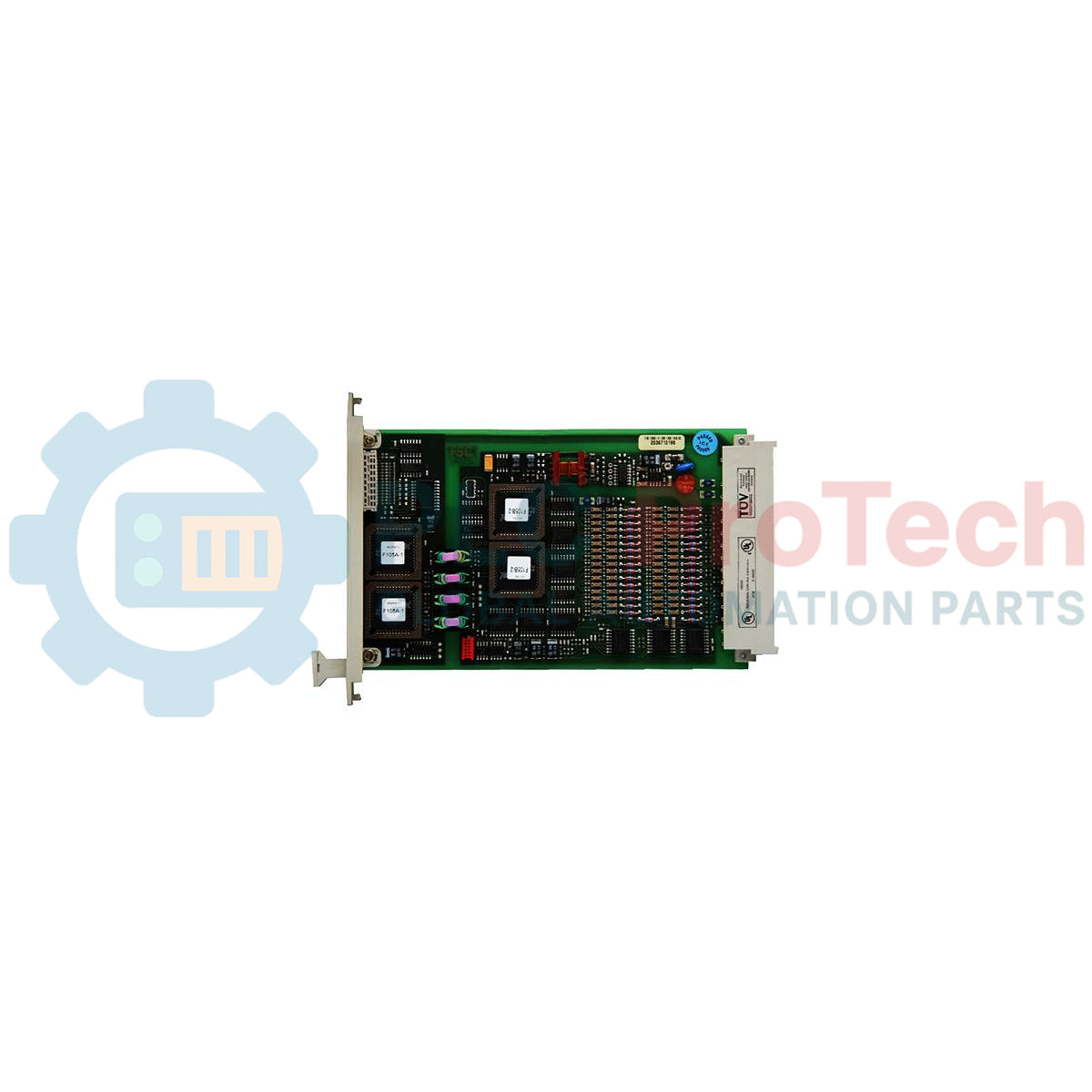
Designed for high-integrity safety instrumented systems (SIS), the Honeywell 10105/2/1 functions as a high-density, fail-safe analog input module within the Fail-Safe Control (FSC) system architecture. This module processes up to 16 safety-critical analog channels operating on a nominal 24 Vdc field supply. To interface with standard industrial transmitters, the high-impedance inputs require external current-to-voltage conversion from 0-20 mA to the module's native 0 to 4.1 V range. This conversion is handled seamlessly through dedicated field termination assemblies or backplane conversion units, maintaining complete galvanic separation and safety loop integrity.
Key Technical Features
-
High-Density Architecture: 16 independent analog input channels in a compact 4 TE width footprint.
-
Safety-Certified Design: Meets safety requirements up to AK1-6 (configured up to AK6 in redundant configurations).
-
High-Resolution Digitization: Integrated 12-bit A/D converter ensuring ±1 LSB accuracy.
-
Flexible Signal Conversion: Compatible with FTA-T-14 field termination blocks or plug-in 10105/A/1 conversion modules.
-
Low Power Consumption: Consumes only 35 mA from the 5 Vdc internal rail and 35 mA from the 24 Vdc system rail.
Industrial Applications
- Emergency Shutdown (ESD) systems in petrochemical processing facilities.
- Burner Management Systems (BMS) in heavy power generation plants.
- Fire and Gas (F&G) detection loops requiring high availability and low error rates.
- Critical loop monitoring in hazardous chemical reactors.
Technical Specifications
| Parameter |
Specification Values |
| Manufacturer |
Honeywell |
| Module Part Number |
10105/2/1 |
| Safety Class Reference |
AK1 through AK6 (AK6 achieved in redundant operation) |
| Required Software Version |
Version 500 or higher |
| Number of Channels |
16 non-isolated input channels |
| Input Voltage Range |
0 to 4.1 Vdc (nominal) |
| Absolute Maximum Input Voltage |
±36 Vdc |
| Input Impedance |
> 1 MOhm |
| System Power Requirements |
5 Vdc at 35 mA; 24 Vdc at 35 mA |
| A/D Converter Resolution |
12-bit (Inaccuracy: ±1 LSB) |
| Total Module Inaccuracy |
< 0.25% of full scale range |
| Crosstalk Between Channels |
> 60 dB |
| Physical Form Factor |
3U Eurocard (4 TE width, 3 HE height) |
| Approvals |
CE compliant; TÜV certified |
| Shipping Weight (Calculated) |
1.5 kg |
Signal Interface Architecture
| Interface Component |
Connection Method / Function |
| FTA-T-14 Module |
External field termination assembly. Directly converts 0-20 mA field loops into the required 0-4.1 Vdc signal using high-precision resistor networks. |
| 10105/A/1 Converter |
Analog input conversion card installed on the programming connector (Px) on the rear side of the 19-inch I/O backplane. |
| External Voltage Readback |
On-board internal diagnostic loops reading back safety-critical voltages to ensure absolute measurement validation. |
Empirical Engineering Insights
Alternative Models & Compatibility
The module requires FSC system software version 500 or higher. Running earlier firmware platforms with this specific physical hardware profile can prevent diagnostic synchronization and fail to initialize safety states. Ensure that the corresponding conversion hardware (such as 10105/A/1) is aligned with the rack assembly before applying power.
Application Pitfalls & Engineering Notes
Because this is a high-impedance (> 1 MOhm) module, attempting to connect a standard raw 4-20 mA transmitter loop directly to the input pins without a conversion assembly (either the FTA-T-14 or 10105/A/1) will cause the input channel to saturate and trigger an open-loop system fault. System designers must ensure that the precision dropping resistors are correctly configured to scale the current signal to the 0 to 4.1 Vdc limits.
Commissioning & Wiring Tips
To guarantee that crosstalk remains above the specified 60 dB limit under noisy conditions, ensure that all field wiring routed from the process transmitters to the FTA module is constructed with high-quality twisted, individually shielded pairs. Connect the cable shields strictly at the instrument side or the safety-earth terminal block on the panel, but never at both ends, to avoid establishing ground loops.
Installation Guidelines
CRITICAL WARNING: SAFETY DE-ENERGIZATION REQUIRED
Always completely switch off active 24 Vdc system power and auxiliary loop power before inserting or extracting this module from the backplane. Hot-swapping without verified bypass controls can result in a safety shutdown of the entire FSC system rack and may damage the sensitive 12-bit ADC inputs.
1
Verify that the backplane slot is free of dust, and inspect the rear Eurocard connectors of the module for bent pins before alignment.
2
Gently slide the module along the designated 4 TE physical subrack guide rails until the backplane connectors sit firmly in place.
3
Tighten the upper and lower faceplate retaining screws to ensure proper grounding and mechanical stability under industrial vibration.
4
Re-apply power, monitoring the system diagnostics panel to verify successful diagnostic checks and the active state of all 16 channels.