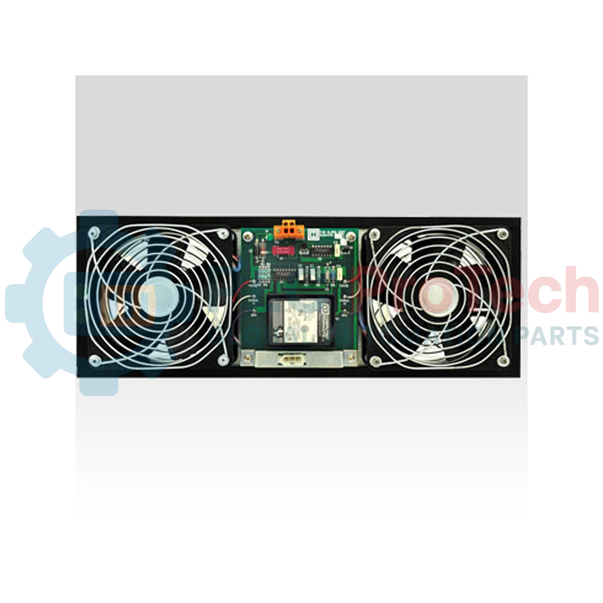
Description
Engineered for thermal regulation within industrial control enclosures, the Honeywell 51303940-250 maintains critical airflow parameters inside TDC 3000 and Experion cabinet systems while providing integrated alarm telemetry. This high-reliability assembly prevents localized thermal hot spots, ensuring the longevity of adjacent PLC, DCS, and power distribution modules. By incorporating a dedicated failure alarm circuit, the unit alerts control room operators immediately upon rotational failure or loss of input power, preventing catastrophic cabinet overheating.
Key Features
- Continuous-duty industrial bearing design optimized for high-uptime environments.
- Integrated alarm telemetry contact for direct interfacing with system monitoring cards.
- Wide voltage input tolerance accommodating fluctuating distribution networks.
- Heavy-duty housing tailored for seamless integration in Honeywell cabinet chassis.
Applications
- Honeywell TDC 3000 system cabinets and marshalling panels.
- Experion PKS hardware enclosure ventilation.
- Critical control rooms requiring continuous thermal management.
Technical Specifications
| Parameter |
Value |
| Manufacturer |
Honeywell |
| Model Number |
51303940-250 |
| Rated Input Voltage |
170-264 VAC |
| Rated Current |
0.5 A |
| Alarm Configuration |
Integrated Rotation/Power Failure Alarm |
| Shipping Weight (Calculated) |
5.0 kg |
Empirical Engineering Insights
This component is critical for preventing thermal runaway in densely packed DCS enclosures. Field telemetry indicates that alarm integration prevents silent fan failures from cascading into module over-temperature shutdowns.
Alternative Models & Compatibility
The 51303940-250 is backward-compatible with legacy TDC 3000 cabinet fan configurations requiring the same footprint. Ensure your cabinet monitor card is configured to recognize the specific impedance or contact signal of this revision to avoid false diagnostics.
Application Pitfalls & Engineering Notes
Operating this unit continuously near its upper limit of 264 VAC in cabinet environments exceeding 55 degC can accelerate bearing degradation. For optimal life expectancy, maintain clean intake filters to prevent backpressure stalls.
Commissioning & Wiring Tips
When wiring the alarm output loop, verify the loop resistance against the system cabinet monitor thresholds. Ensure ground shielding is maintained across the power cabling to prevent induced EMI in sensitive analog I/O cards sharing the same wire duct.
Installation Guidelines
CRITICAL WARNING
Isolate and lock out all AC power distribution sources feeding the cabinet fan assembly before beginning physical installation. High voltages up to 264 VAC are present on the terminal connectors. Allow fan blades to come to a complete stop and verify the circuit is de-energized with a calibrated voltmeter.
1
Mount the fan assembly securely to the cabinet ventilation plate using standard industrial fastening hardware, ensuring correct airflow direction markers face outward.
2
Connect the AC power supply wiring to the input terminals, adhering to designated line, neutral, and ground terminal allocations.
3
Route the alarm telemetry contacts to the cabinet's internal monitoring unit or input terminal block, ensuring segregation from high-voltage AC cables.