Description
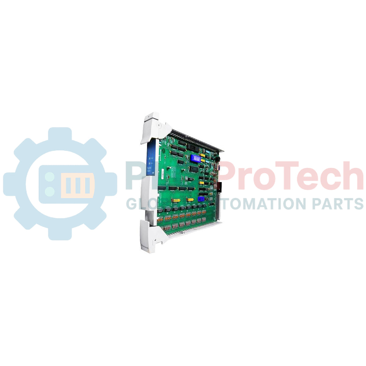
Managing binary field signals within industrial process environments, the Honeywell 51304485-100, also designated as the MU-PDIX02, serves as a high-density digital input processor card for TDC 3000 and Experion control systems. This printed wire assembly (PWA) is engineered to interface field-side digital inputs directly with the High Performance Process Manager (HPM) or Advanced Process Manager (APM) backplane, translating discrete state changes into system logic. Featuring a conformal-coated (CRP) finish, this module provides superior protection against moisture, dust, and corrosive airborne contaminants typical of chemical plants and refinery control rooms.
Key Features
-
Conformal Coated PWA: Certified CRP (corrosion protection) processing shields sensitive surface-mount components from aggressive industrial atmospheres.
-
Optocoupler Isolation: Protects internal system control logic from high-voltage field-side surges and electrical transients.
-
Fast State-Change Capture: Provides high-speed scanning of discrete contact inputs for reliable alarms and Sequence of Events (SOE) tracking.
-
High-Density Architecture: Maximizes cabinet slot efficiency by accommodating multiple digital input channels per card.
-
Direct System Integration: Fully compatible with Honeywell legacy chassis configurations and modern Experion HPM migration architectures.
Applications
-
Refined Petrochemical Operations: Valve position switch monitoring and limit-state verification.
-
Power Generation Systems: Monitoring electrical trip systems, breaker states, and generator status indicators.
-
Pulp and Paper Mills: Dry-contact input interfacing from motor control centers (MCC) and safety interlock switches.
-
Water/Wastewater Treatment: Remote level switch, pump run status, and system error contact aggregation.
Technical Specifications
| Parameter |
Specification Value |
| Manufacturer |
Honeywell |
| Model Designation |
MU-PDIX02 |
| Part Number |
51304485-100 |
| Module Type |
Digital Input Processor PWA |
| Environmental Protection |
Conformal Coated (CRP - Corrosion Resistant Product) |
| System Compatibility |
TDC 3000 / Experion PM, APM, HPM Systems |
| Interface Connection |
High-density ribbon connector to Field Termination Assembly (FTA) |
| Operating Temperature Range |
0 to 60 degC |
| Storage Temperature Range |
-40 to 85 degC |
| Shipping Weight (Calculated) |
4.0 kg |
| Package Dimensions (Calculated) |
32.0 x 25.0 x 6.5 cm |
Empirical Engineering Insights
Alternative Models & Compatibility
The MU-PDIX02 serves as a direct upgrade to non-conformal coated variations (such as the standard MU-PDI02 or older revision variants). When performing a drop-in replacement, ensure that the corresponding Field Termination Assembly (FTA) and cable connectors are checked for oxidation, as legacy pins are susceptible to surface degradation over multi-decade cycles.
Application Pitfalls & Engineering Notes
In enclosed cabinet assemblies containing dense card racks, localized heat build-up can lead to premature optocoupler drift. Maintaining functional cabinet fan assemblies is critical. Ensure that any unpopulated card slots adjacent to the card are covered with blanking panels to maintain proper vertical air routing across the PWA surface.
Commissioning & Wiring Tips
Always verify that the shield drain wire of the input field cable is terminated strictly at the FTA chassis ground point and not at both ends. Dual-point grounding introduces ground loops that can manifest as intermittent digital state oscillation or false alarms within the logic supervisor.
Installation Guidelines
CRITICAL WARNING
Before inserting or extracting the processor card, completely isolate all system-side and field-side power sources. Static discharge precautions must be strictly observed. Wear an approved, grounded ESD wrist strap throughout the handling and installation process to prevent non-reversible damage to internal CMOS components.
1
Power down the specific card slot by verifying the backplane status LEDs and isolating the local field termination power source.
2
Verify that the plastic card guides are clear of debris and that the card backplane socket pins are completely straight and undamaged.
3
Gently align the card edges with the slot tracks and push firmly until the card is fully seated in the backplane connector. Secure the module retaining mechanisms.
4
Reconnect the FTA cable harness, restore input power, and perform the standard point-to-point diagnostic verification via the supervisor terminal.