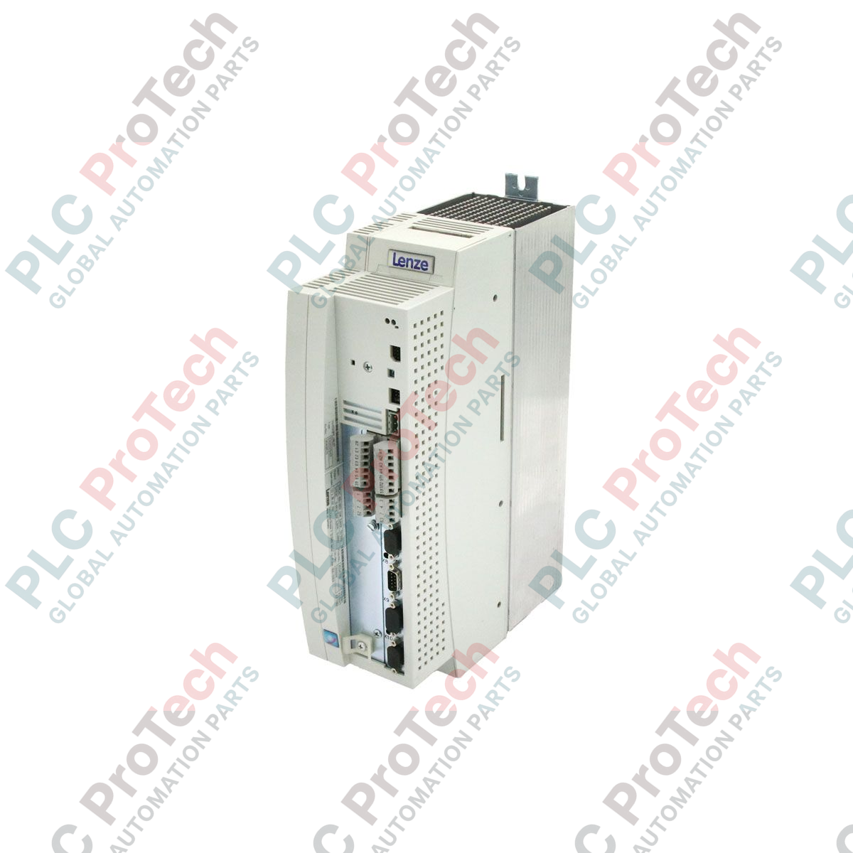
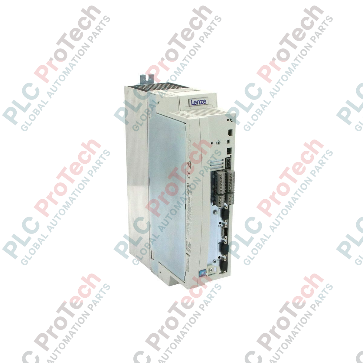
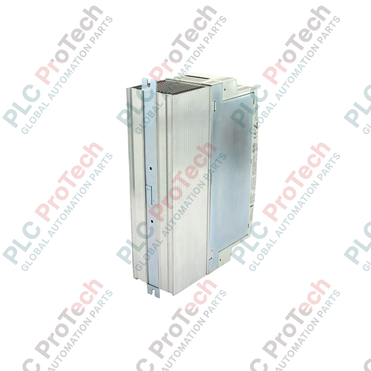
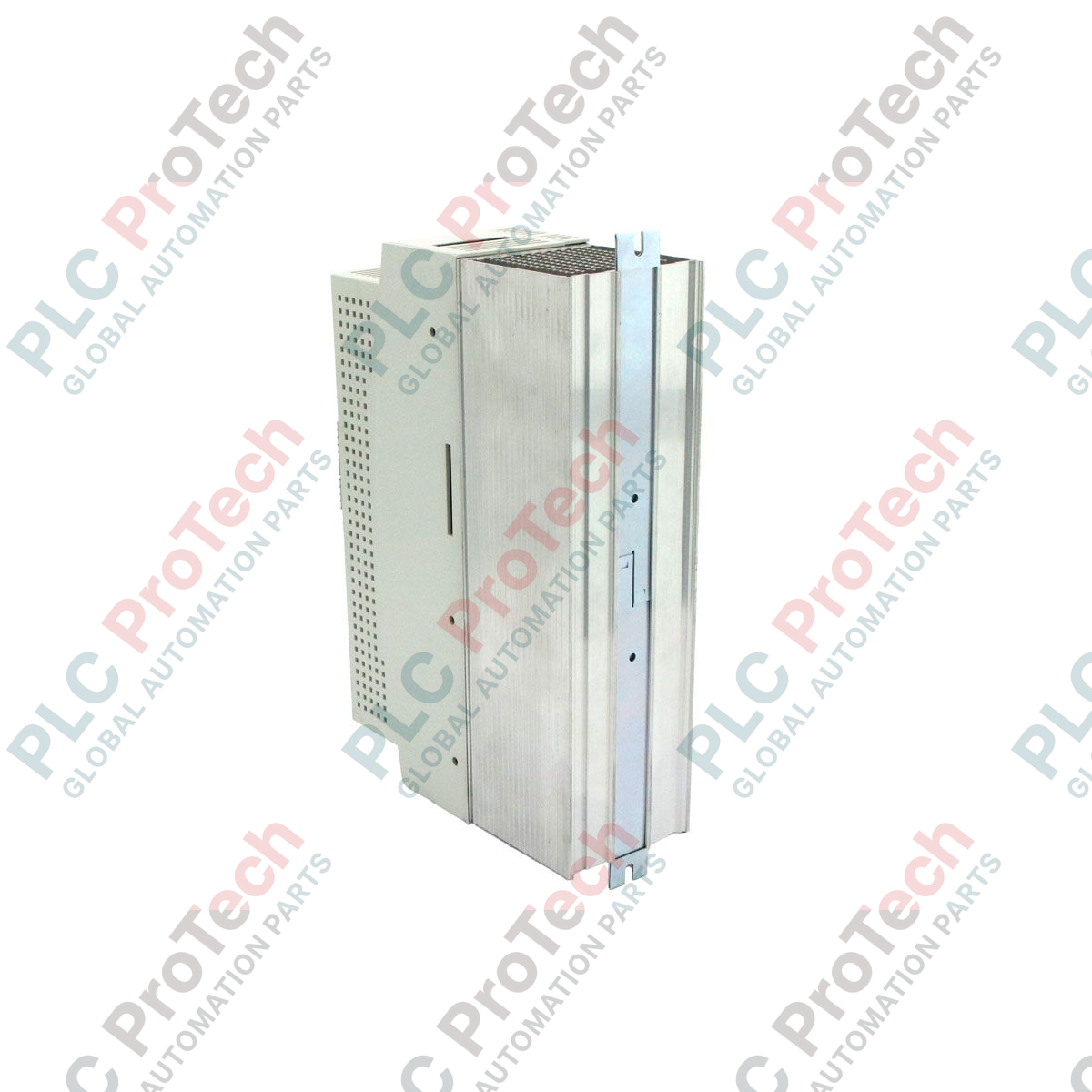
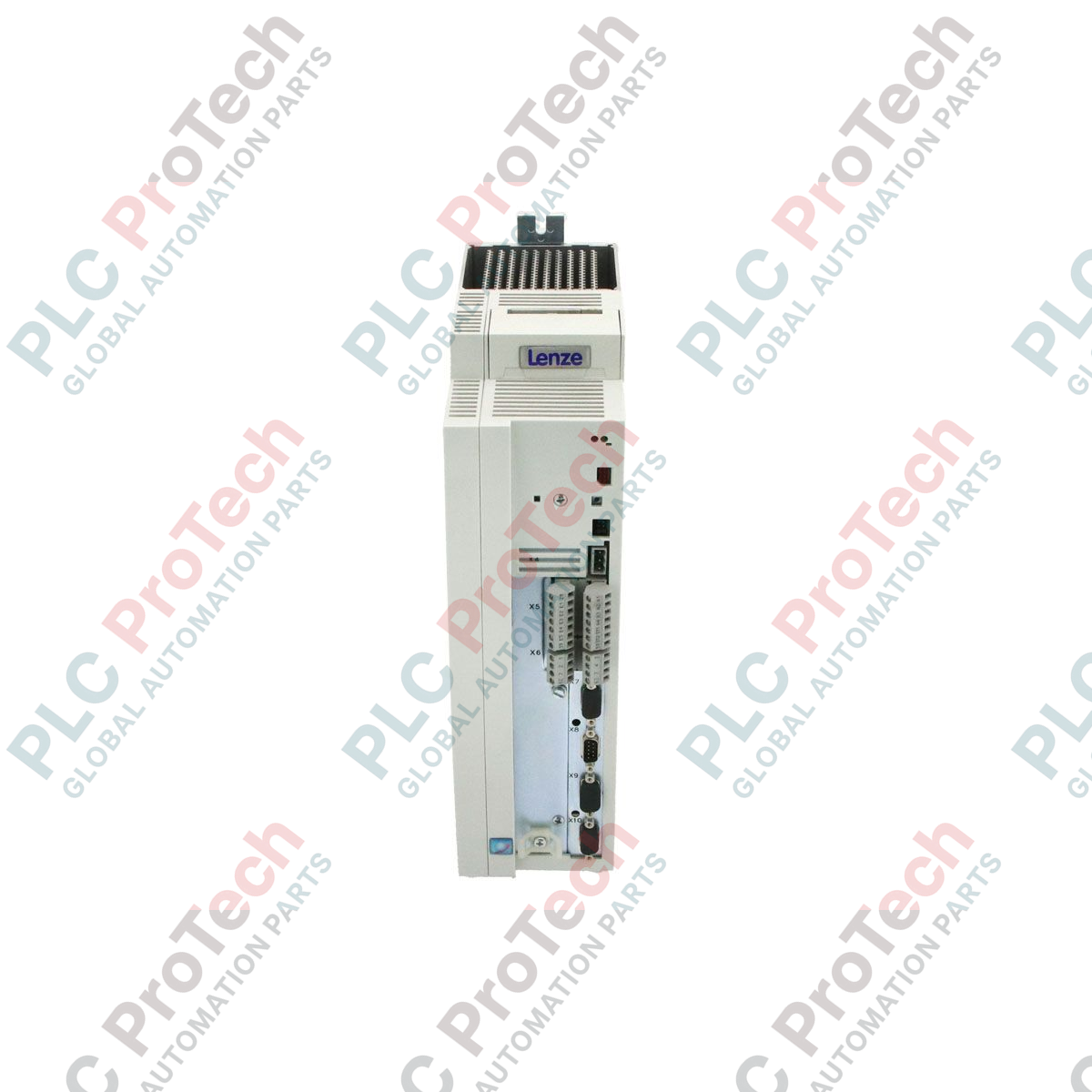
Projetado para controle preciso de movimento e tarefas de posicionamento dinâmico em ambientes industriais automatizados, o Lenze EVS9323-EP atua como um controlador servo de posição de alto desempenho dentro da família Série 9300. Esta unidade integra-se perfeitamente em arquiteturas de controle centralizadas ou descentralizadas, fornecendo controle robusto em malha fechada para motores servo AC síncronos e assíncronos. Projetado com grau de proteção IP20, é otimizado para instalação vertical em painéis elétricos protegidos, garantindo gerenciamento térmico confiável e estabilidade operacional a longo prazo em processos de fabricação exigentes.
Principais Características
-
Controle de Posicionamento Integrado: Geradores de perfil e registradores de posição embutidos suportam perfis de movimento complexos, rotinas de referência e sequências de posicionamento alvo sem necessidade de módulos PLC externos de alta velocidade.
-
Interface de Barramento do Sistema: Integração nativa do barramento CAN para comunicação de alta velocidade entre múltiplos drives, controladores e sistemas supervisórios HMI.
-
Suporte Flexível de Feedback: Compatível com sistemas padrão de resolvers e codificadores de alta resolução para feedback preciso de velocidade e posição.
-
Gerenciamento Térmico: Projetado para montagem vertical com geometria otimizada do dissipador de calor para facilitar o resfriamento eficiente por convecção natural ou forçada.
-
Expansão Modular: Suporta módulos de comunicação plugáveis (AIF) para integração em PROFIBUS, Interbus ou outras redes industriais de campo.
Aplicações
-
Máquinas de Embalagem: Indexação de alta velocidade, cortadores rotativos e sistemas de engrenagem eletrônica.
-
Manuseio de Materiais: Sistemas automatizados de armazenamento e recuperação (ASRS), pontes rolantes e carrinhos de transferência de alta velocidade.
-
Montagem & Robótica: Sistemas multi-eixo de pick-and-place, robôs cartesianos e mesas indexadoras rotativas precisas.
-
Processamento Têxtil: Enrolamento controlado por tensão, desenrolamento e controle sincronizado do eixo de alimentação.
Especificações Técnicas
| Parâmetro |
Valor / Especificação |
| Fabricante |
Lenze |
| Número do Modelo |
EVS9323-EP |
| Série |
Série 9300 |
| Tipo de Dispositivo |
Controlador de Posição Servo |
| Potência Nominal de Saída |
1,5 kW |
| Grau de Proteção |
IP20 |
| Dimensões (L x A x P) |
10,20 cm x 35,60 cm x 25,40 cm |
| Peso |
4,90 kg |
| Código da Mercadoria |
85044095 |
| Classificação de Controle de Exportação (ECCN) |
N |
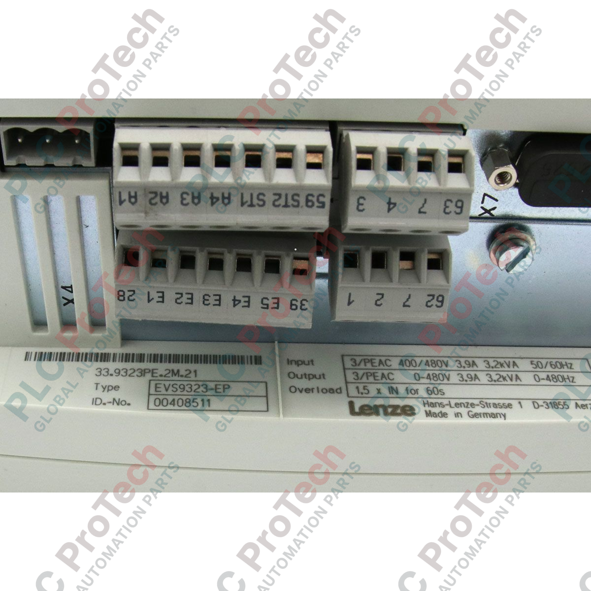
Conexões e Interfaces
| Terminal / Porta |
Função / Atribuição de circuito |
| X1 |
Entradas e saídas analógicas (pontos de ajuste de velocidade/torque, monitoramento) |
| X2 |
Entradas e saídas digitais (início, parada, chaves de limite, status pronto) |
| X4 |
Barramento do sistema CAN (conexão do barramento do sistema, sincronização) |
| X11 |
Entrada do resolver (conexão de feedback do motor) |
| Slot AIF |
Interface de Automação para módulos de comunicação plugáveis (ex.: PROFIBUS) |
Insights Empíricos de Engenharia
Modelos Alternativos e Compatibilidade
O EVS9323-EP é configurado especificamente como controlador de posição. Não deve ser confundido com o EVS9323-ES (variante controlador de velocidade) ou o EVF9323 (inversor de frequência). Ao substituir revisões antigas de hardware, verifique se a versão do firmware da unidade substituta corresponde ou é superior à original para garantir compatibilidade com os conjuntos de parâmetros Global Drive Control (GDC) e configurações de fieldbus existentes.
Armadilhas de Aplicação e Notas de Engenharia
Em aplicações que envolvem ciclos de desaceleração rápida ou cargas de alta inércia, a capacitância interna do barramento DC pode ser insuficiente para absorver a energia regenerativa. Para evitar falhas por sobretensão (normalmente indicadas pelo código de falha OU), um resistor de freio externo deve ser dimensionado e conectado nos terminais de alimentação apropriados. Garanta um espaço livre adequado de pelo menos 100 mm acima e abaixo do inversor dentro do gabinete para evitar acúmulo térmico.
Dicas de Comissionamento e Fiação
Sempre use cabos de par trançado com dupla blindagem para as interfaces de feedback do resolver (X11) e do barramento do sistema CAN (X4). A blindagem deve ser aterrada com conexões de baixa impedância diretamente na placa de montagem usando grampos de aterramento. Evite passar cabos de controle e feedback paralelos a cabos de alimentação de motor de alta tensão para mitigar problemas de interferência eletromagnética (EMI).
Diretrizes de Instalação
AVISO CRÍTICO: Garanta a desenergização física completa da alimentação principal antes de manusear. Os capacitores do barramento DC retêm tensões letais (até 800V DC) após o desligamento. Aguarde no mínimo 5 minutos para que a carga residual se dissipe a níveis seguros (< 50V DC) antes de iniciar qualquer procedimento de fiação, conexão de terminais ou inspeção. Verifique com um multímetro calibrado.
1
Monte o controlador verticalmente em uma placa traseira plana e livre de vibrações dentro de um gabinete de controle com classificação IP54 ou superior para manter a classificação de proteção IP20.
2
Conecte o condutor de terra de proteção (PE) ao terminal de aterramento designado antes de fazer qualquer outra conexão elétrica.
3
Ligue os terminais de alimentação do motor (U, V, W) e o resolver de feedback (X11) usando cabos blindados, garantindo a terminação adequada da blindagem na placa de aterramento do inversor.
4
Complete a fiação de controle (X1, X2) e configure os resistores de terminação da rede CAN (120 Ohm) se a unidade estiver posicionada na extremidade física do segmento da rede.